GROVE 8-21
CD3340B/YB4411 AXLES/DRIVE SHAFTS/WHEELS AND TIRES
Published 04/07/2015 Control # 569-00
Assembly
Pinion Assembly
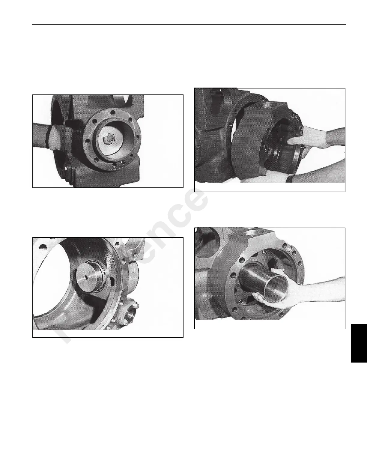
1. Place the center housing on a work bench. Using
SPECIAL TOOL P/N 1901782, press the taper roller
bearing cups (Figure 8-81) into the center housing until
they seat.
2. SPECIAL TOOL P/N 1901775 (False Pinion) is needed
for this procedure. Insert the false pinion, together with
its bearings and ring nut, in the bearing cups in the
housing (Figure 8-82) installed in step 1. Tighten the
assembly to remove any play (backlash) in the
assembly.
3. Check the correct positioning of the right and left brake
flanges, using the reference marks on them and the
center housing (Figure 8-83).
Assemble the two brake flanges and secure them with
their mounting screws (screw in at least two screws,
diametrically opposed to each other in each flange).
4. Insert SPECIAL TOOL P/N 1901778 (false differential
box) into the center housing (Figure 8-84). Check that
the false differential box is inserted into both brake
flange housings.
Reference Only
 Loading...


