AXLES/DRIVE SHAFTS/WHEELS AND TIRES CD3340B/YB4411
8-22
Published 04/07/2015 Control # 569-00
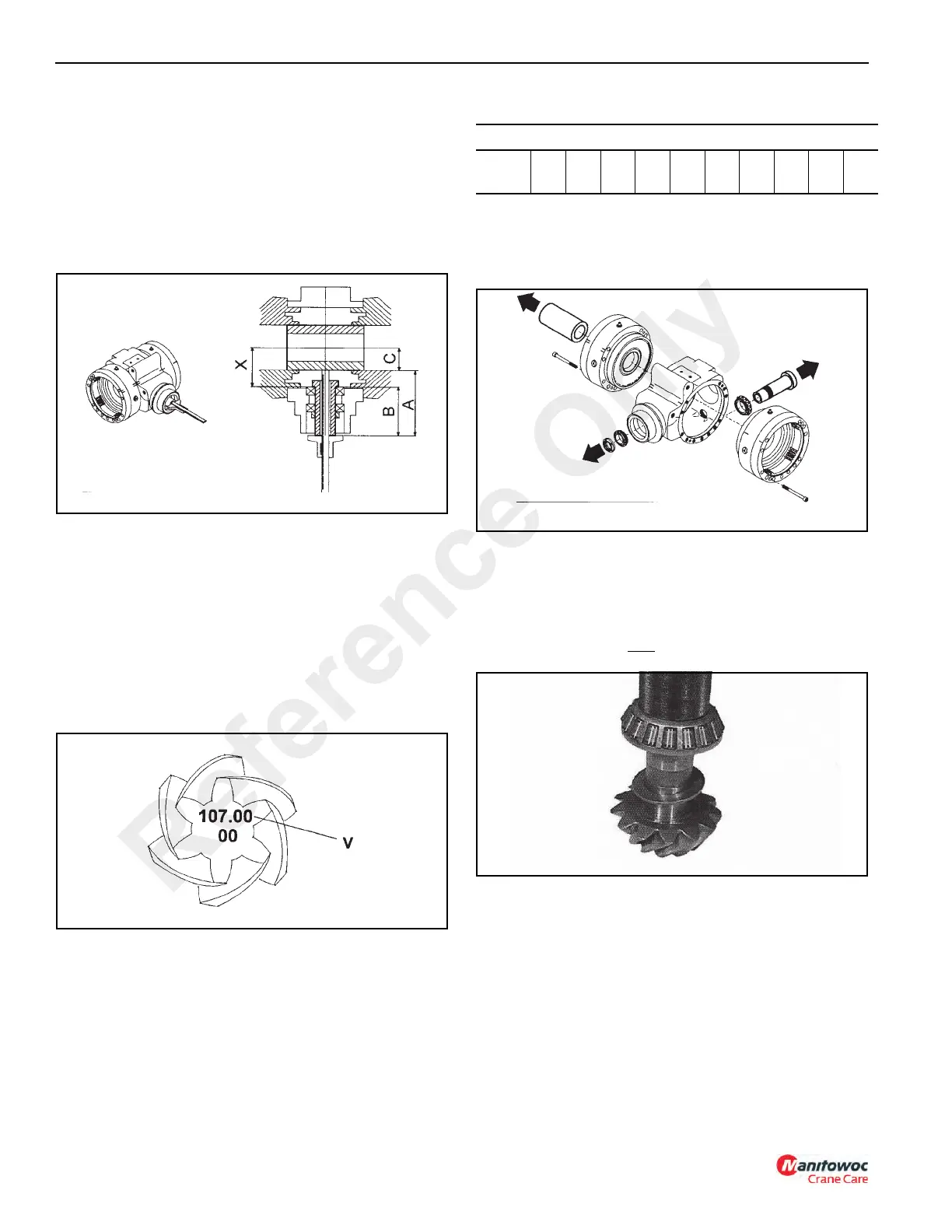
5. Measure the distance measurements described below
using a depth gauge through the hole in the false pinion
(Figure 8-85).
X = (conical distance to be measured)
A = (measured value)
B = (known value - 100 mm)
C = (known value - 45 mm)
Measured values all millimeters.
6. To determine the amount of shims (S) required between
the pinion and bearing perform the following calculation:
a. Subtract the (V - requested conical distance) value
stamped on the pinion head (Figure 8-86) from the
measured (X) value.
S=X-V
b. (X) value is found by adding measurements (A and
C) together and subtracting B.
X=(A+C)-B
7. Choose the suitable shim from the available shims in
Table 6-1. Shims may be found in the parts manual
supplied with the crane.
Table 8-2.
8. Remove the false pinion, the bearings and the ring nut
from the center housing (Figure 8-87). Remove the false
differential box from the center housing. Remove the two
brake flanges from the center housing.
9. Insert the shims (S) chosen in step 7 on the pinion shaft
with the chamfer edge against the gear (Figure 8-88).
Using SPECIAL TOOL P/N 1901772 press the bearing
onto the pinion shaft. Be sure it is fully set. Install the
washers and new elastic spacer onto the shaft.
NOTE: Always use a new
elastic spacer.
10. Insert the bevel pinion assembly into the center housing
and the second bearing cone onto the pinion end
(Figure 8-89).
In order to properly install the bearing use SPECIAL
TOOL P/N 1901772 and a hammer to drive the bearing
into position. Hold a sledge hammer against the gear
while driving the bearing.
S = SHIM RANGE
Thick
(MM)
2.5 2.6 2.7 2.8 2.9 3.0 3.1 3.2 3.3 3.4
Reference Only
 Loading...


