GROVE 8-23
CD3340B/YB4411 AXLES/DRIVE SHAFTS/WHEELS AND TIRES
Published 04/07/2015 Control # 569-00
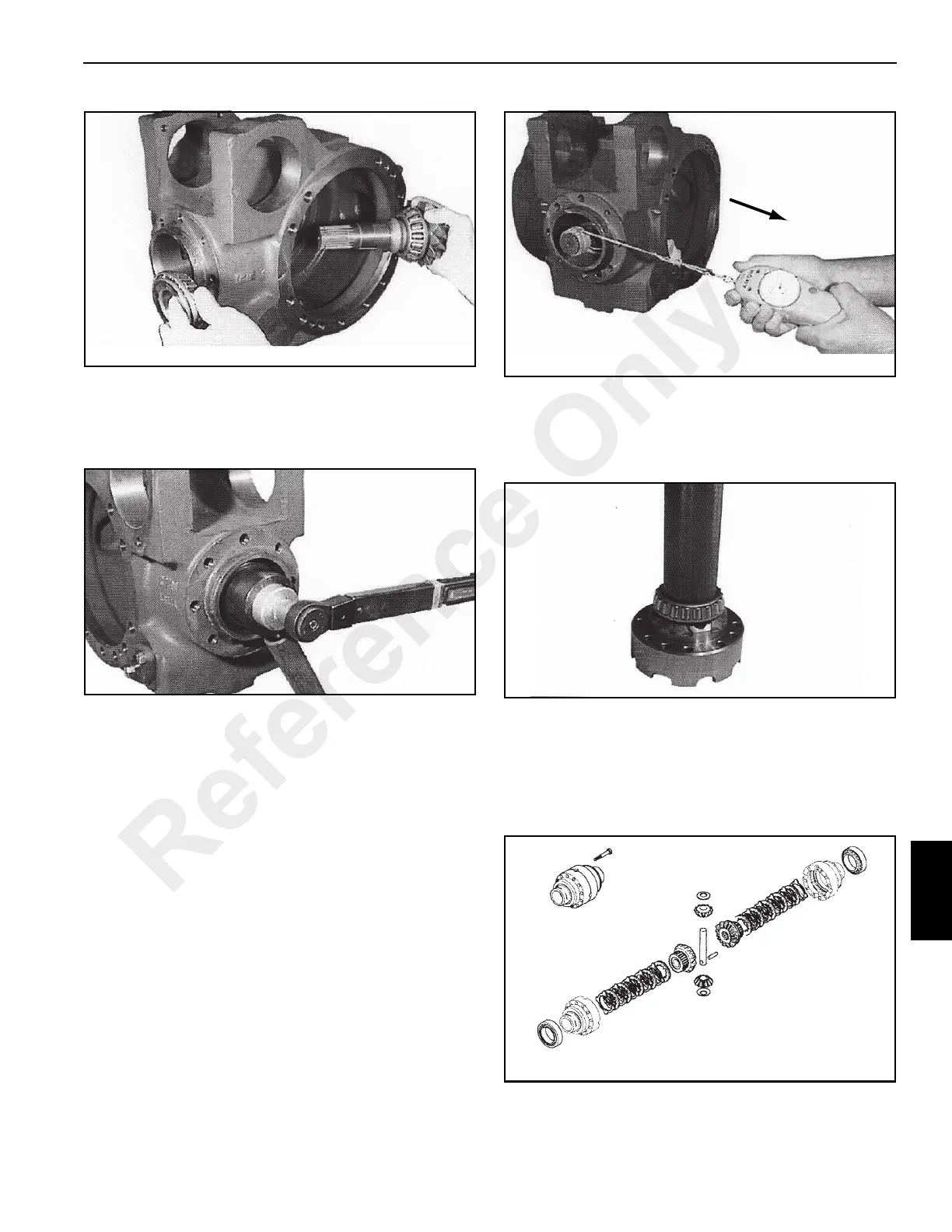
11. Assemble onto the pinion shaft a new ring nut washer
and ring nut retainer.
Screw the ring nut in, using SPECIAL TOOLS P/N
1901768 and P/N 1901773 (Figure 8-90).
NOTE: The torque setting is determined by the pre-loading
measurement on the bearings. Tighten the ring nut
step by step. If it is tightened too much, the elastic
spacer should be replaced and the procedure
repeated. When checking the pre-load, it is
advisable to hit the pinion ends slightly with a soft
hammer to set the bearings.
12. To check the bearing pre-load, use a dynamiter and
string. Wind the string around the spline end of
SPECIAL TOOL (P/N 1901772) inserted on the pinion
shaft (Figure 8-91).
NOTE: The pre-load measurement should be done without
the seal ring installed.
With the dynamiter attached to the string, pull the
dynamiter and take a reading. Tighten or loosen the ring
nut until 9.2 - 13.8 daN (20 - 31 pounds) of force is
required to turn the pinion. When the correct turning
force is obtained, peen the ring nut using a hammer and
a chisel.
P = 9.2 - 13.8 daN
(20 - 31 pounds)
Differential Assembly
1. Install the bearing cones of the new taper roller bearings
on the differential housing halves (Figure 8-92). Use
SPECIAL TOOL P/N 1901771 and a hammer.
2. Place a housing half on a work bench and assemble all
of its inner components (discs, counterdiscs, planetary
gears, sun gears, thrust washers and pins) as shown in
Figure 8-93.
Join the two housing halves, aligning the reference
marks made during disassembly.
Reference Only
 Loading...


