SETUP AND INSTALLATION MLC165-1 OPERATOR MANUAL
4-24
Published 08-06-19, Control # 237-09_v2
6. Lower the crawler so the alignment pins (3, Figure 4-20)
engage the alignment saddles (4). Continue to lower the
crawler until the lifting slings go slack.
7. Using the carbody control, engage the crawler pins (3,
Figure 4-21
).
8. Remove the collars (1, Figure 4-21
) from the storage
lugs (2) and assemble the collars to the end of the
crawler pins (3).
9. Disconnect the lifting slings from the crawler.
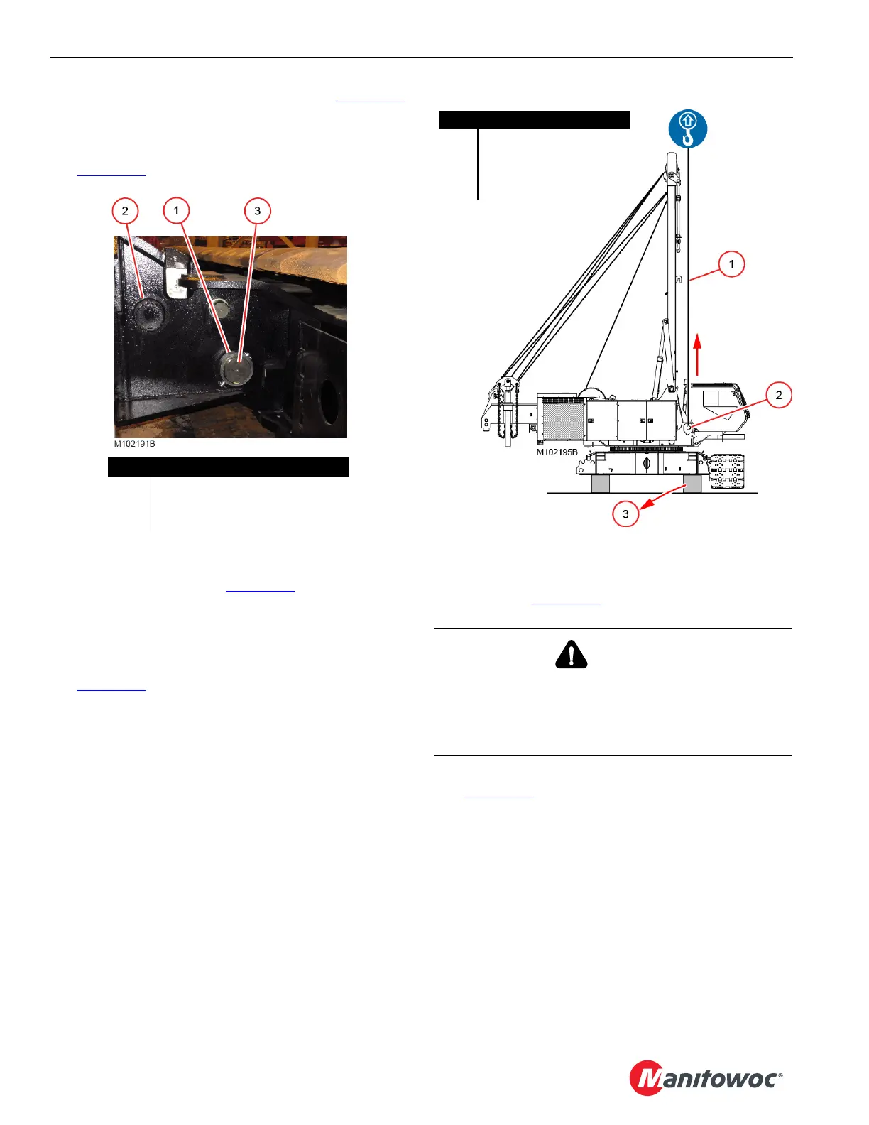
10. Attach owner furnished synthetic lifting slings (1,
Figure 4-22
) to the boom hinge pins (2).
• Boom hinge pins should be engaged
• Slings can be either basketed or chocked
• Sling length should be at least 15 ft (5 m) long
• Sling capacity is at least 54,000 lb (24 494 kg)
Use caution to prevent the slings from being
damaged by the edges of the boom hinge plates on
the rotating bed.
11. Lift the crane only enough to loosen the load on the
blocking (3, Figure 4-22
) and remove the blocking.
12. Lower the crane until the crawler is on the ground
(Figure 4-23
) and the lifting slings slacken.
13. Disconnect the lifting slings from the boom hinge pins.
Figure 4-21
Item Description
1 Collar with Pin and Safety Pins (2)
2 Storage Lug (2)
3 Crawler Pin (2)
ENGAGED
DANGER
Tipping Hazard!
Swing is prohibited while the crane is on blocking.
Do not swing the MLC165-1 upperworks until after the first
crawler is installed and resting on the ground.
Figure 4-22
Item Description
1 Owner Furnish Synthetic
Slings
2 Boom Hinge Pin (2)
3 Blocking
 Loading...


