INSTALLATION
3-9
MA-5079-ENG MICRON GEAR ADHESIVE MELTER
• Output disabled_disabled input signal for each hose-applicator output
via a non-voltage contact. With a closed contact, the output remains
activated (output on); with an open contact, it is deactivated (output off).
• Motor start up_for each pump installed, the motor start up may be
controlled by closing an external non-voltage contact.
• Motor speed set point_for each pump installed, the rotational speed of
the motor (and therefore, the pump) may be controlled by means of a 0
to 10V DC external signal.
• Failures output in pump control card_output from a non-voltage
contact that communicates normally to a warning light beacon the
failure from the pump control card.
Warning: Risk of electric shock. Carelessness may cause injuries or death.
If any of these signals are to be connected, open the electrical cabinet for
greater convenience while carrying out this task. To do this, follow the steps
outlined below:
1. Remove the electrical cabinet casing following the instructions given
in the maintenance section ‘Removal and replacement of casing
elements’.
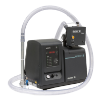
2. Open the electrical cabinet side panel by loosening the screw indicated.
Use Allen wrench 3.
Temperature ok
1. If only this signal will be connected, use a 0.5 mm
2
two-wire cable.
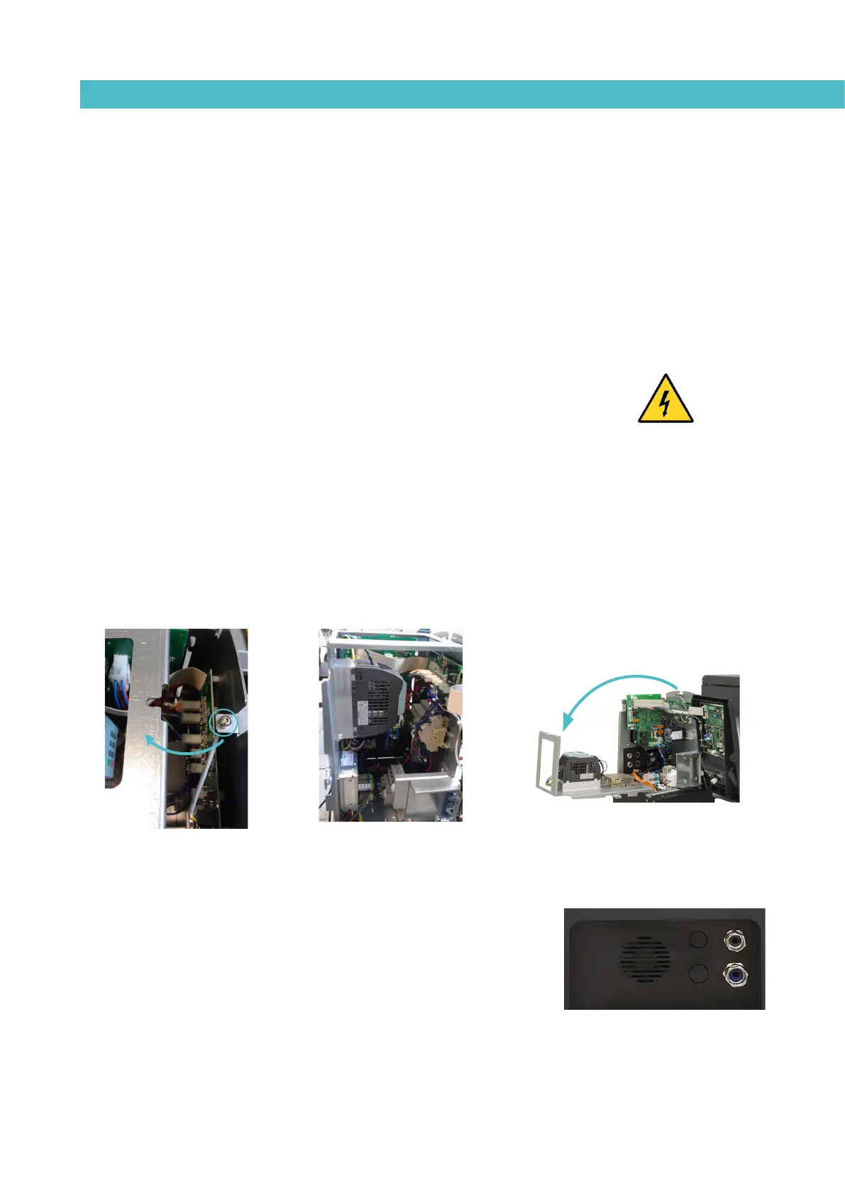
Install an electrical wall bushing Pg13.5 next to the electrical supply
input.
2. Thread the power cord (max. Ø12.5mm) through the electrical wall
bushing Pg13.5 and fasten it to the inside anchor, making sure that the
cord reaches the power card connector.