FOCKE MELER GLUING SOLUTIONS
4-32
MELTER OPERATION
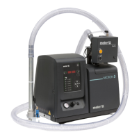
Current Vin voltage display
Whenever the Vin key is held pressed, the three digits on the right will show
the input voltage reading to one decimal point.
If the values for any point in the speed ramp table is being edited, and the Vin
key is held pressed for 3 seconds, the voltage value which is operating at this
time it will be copied to that value on the table.
By-pass valve regulation
The pumping system using a geared pump provides a constant flow of
adhesive, according to the pump’s rotational speed.
In this type of system, the pressure generated by the pump is the result of the
retentions found on the circuit (the length and diameter of the hose, elbows
in the connectors, the diameters of the nozzle outputs, etc.) and the adhesive
itself (its viscosity).
For safety reasons, this pressure must be discharged when the circuit exceeds
the operating value (normally with a closed circuit and the pump activated),
which makes the use of a discharge valve or a by-pass valve necessary.
This valve may be a manual adjustment valve, using a threaded screw, or
with pneumatic control, using a pressure regulator and a pressure gauge. In
the latter case, the adhesive circuit pressure has a 1:13 ratio to the pressure
displayed on the pressure gauge.
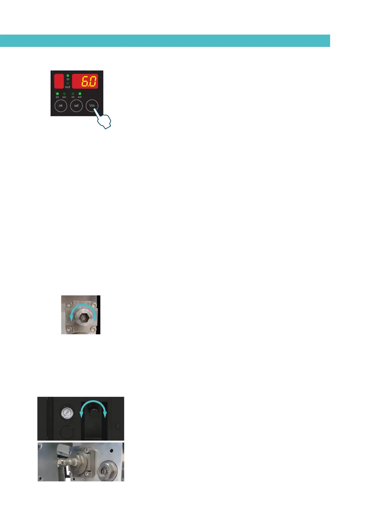
Manual valve control
To adjust the pressure with this valve model (in an approximate manner),
follow these steps:
1. Screw the spindle in clockwise, as far as possible. In this position, the
maximum pressure is 81,5 kg/cm
2
(8,82 bar).
2. Gradually loosen by turning counterclockwise until reaching the
desired pressure. Each millimeter that the spindle sticks out
represents a reduction of approximately 9 kg/cm
2
(8,82 bar).
Pneumatic valve control
To adjust the pressure with this valve model, follow these steps:
1. Unlock the pressure regulator control by pulling on it gently.
2. Turn it clockwise to increase the pressure. This will be seen reflected
on the pressure gauge located next to it.