MELTER OPERATION
4-23
MA-5079-ENG MICRON GEAR ADHESIVE MELTER
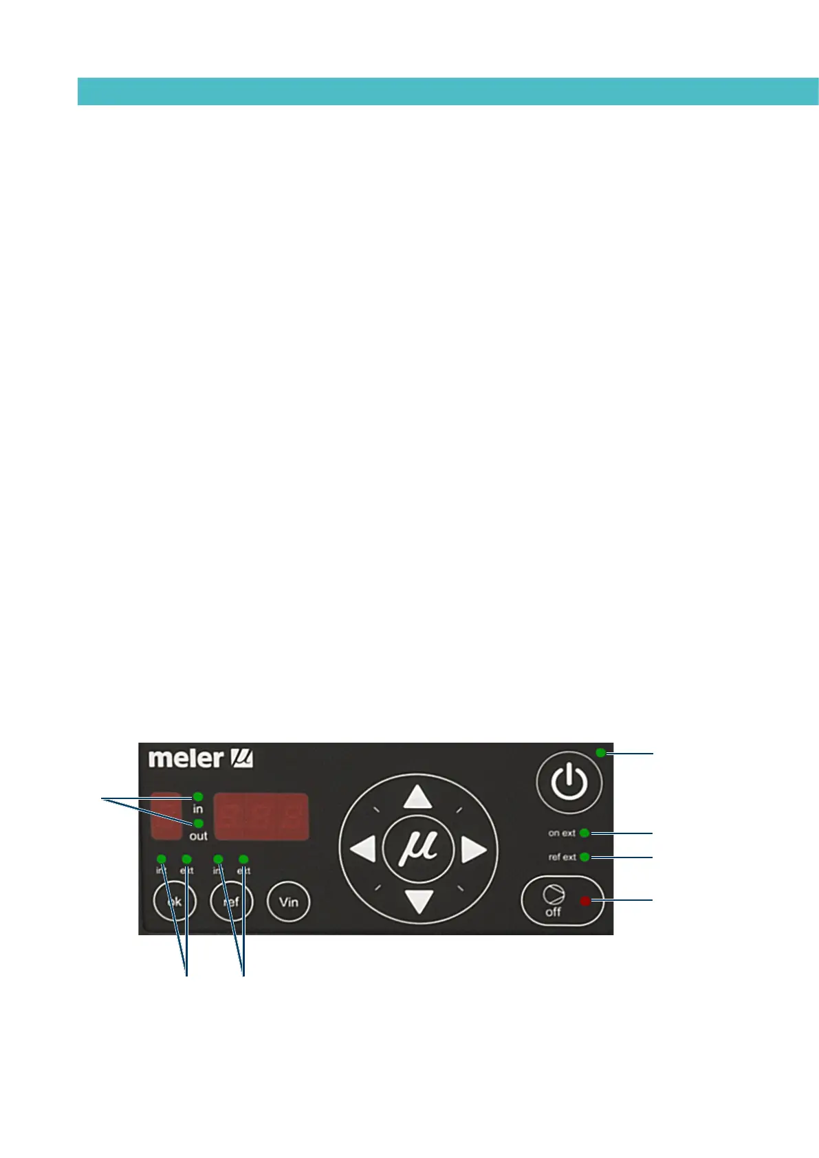
LED indicators
Described below are the LED indicators on the pump control card to identify
the status of the equipment:
1. Control card ON/OFF LED: when the external 24 Vdc power supply is
present, this LED will always be illuminated; with no power supply, it will be
turned off. This LED is green in colour.
2. Pumping ON/OFF LED: when pumping is enabled, this LED will be turned off,
and will be illuminated when pumping is disabled. This LED is in colour.
3. Int and ext (ok) LEDs: when the equipment is operating in Internal start-stop
(ok) mode, the ‘int’ LED will be illuminated and the ‘ext’ LED will be turned off.
When the equipment is operating in external start-stop (ok) mode, the ‘ext’ LED
will be illuminated. And the ‘int’ LED will be turned off. These can never be both
on or both off at the same time. These LEDs are green in colour.
4. Int and ext (ref) LEDs: when the equipment is operating in internal
reference mode, the ‘int‘ LED will be illuminated and the ‘ext’ LED turned off.
When the equipment is operating in external reference mode, the ‘ext’ LED
will be illuminated and the ‘int’ LED will be turned off. These can never be
both on or both off at the same time. These LEDs are green in colour.
5. Ext on LED: when the equipment is operating in external start-stop
(OK) mode, and the external permission contact is closed, this LED will be
illuminated; if the external contact is open, this LED is turned off. This LED is
green in colour.
6. Ext ref LED: when operating in external reference mode and the external
reference voltage is other than zero, this LED will be illuminated. When the external
reference voltage is zero, this LED will be turned off. This LED is green in colour.
7. In/Out LED: when operating in external set point reference mode, these LEDs
will be activated and deactivated as the speed ramp options are programmed.
These LEDs are green in colour.
1
7
43
2
6
5