MELTER OPERATION
4-31
MA-5079-ENG MICRON GEAR ADHESIVE MELTER
Programming speed ramp
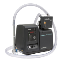
To access this menu and program the different points corresponding to the voltage-
speed ratio, you must select external reference (‘ref ext’ LED is illuminated) and
press the right arrow key. Then the following message is displayed:
The IN LED to the position ON and the OUT LED to the position OFF, 1 000,
NOT EDITABLE; press the right arrow to go to the next point:
The IN LED to the position OFF and the OUT LED to the position ON, 1 XXX,
which means that the output speed is being programmed for point 1 (when the
input voltage is 0 V); with the up/down arrow keys the value may be modified,
within a range from 000 to MAXIMUM RPM; press the right arrow key to go to
the next point:
The IN LED to the position ON and the OUT LED to the position OFF, 2 XXX,
which means that the input voltage value is being programmed for point 2; with
the up/down arrow keys the value may be modified, within a range from 00.0 to
10.0 (to one decimal place); press the right arrow key to go to the next point:
The IN LED to the position OFF and the OUT LED to the position ON, 2 XXX,
which means that the output speed value is being programmed for point 2;
with the up/down arrow keys the value may be modified, within a range from
000 to MAXIMUM RPM; press the right arrow key to go to the next point:
The IN LED to the position ON and the OUT LED to the position OFF, 3 XXX,
which means that the input voltage value is being programmed for point 3; with
the up/down arrow keys the value may be modified, within a range from 00.0 to
10.0 (to one decimal place); press the right arrow key to go to the next point:
The IN LED to the position OFF and the OUT LED to the position ON, 3 XXX,
which means that the output speed value is being programmed for point 3;
with the up/down arrow keys the value may be modified, within a range from
000 to MAXIMUM RPM; press the right arrow key to go to the next point:
The IN LED to the position ON and the OUT LED to the position OFF, 4 XXX,
which means that the input voltage value is being programmed for point 4; with
the up/down arrow keys the value may be modified, within a range from 00.0 to
10.0 (to one decimal place); press the right arrow key to go to the next point:
The IN LED to the position OFF and the OUT LED to the position ON, 4 XXX,
which means that the output speed value is being programmed for point 4;
with the up/down arrow keys the value may be modified, within a range from
000 to MAXIMUM RPM; press the right arrow key to go to the next point:
The IN LED to the position ON and the OUT LED to the position OFF, 5 100,
NOT EDITABLE; press the right arrow key to go to the following message:
The IN LED to the position OFF and the OUT LED to the position ON, 5 XXX,
which means that the speed value is being programmed for point 5; with the
up/down arrow keys the value may be modified, within a range from 000 to
MAXIMUM RPM; press the right arrow key to exit the menu.
Press the right arrow key to return to the menu, and the initial message is
displayed: The IN LED to the position ON and the OUT LED to the position ON,
1 000.
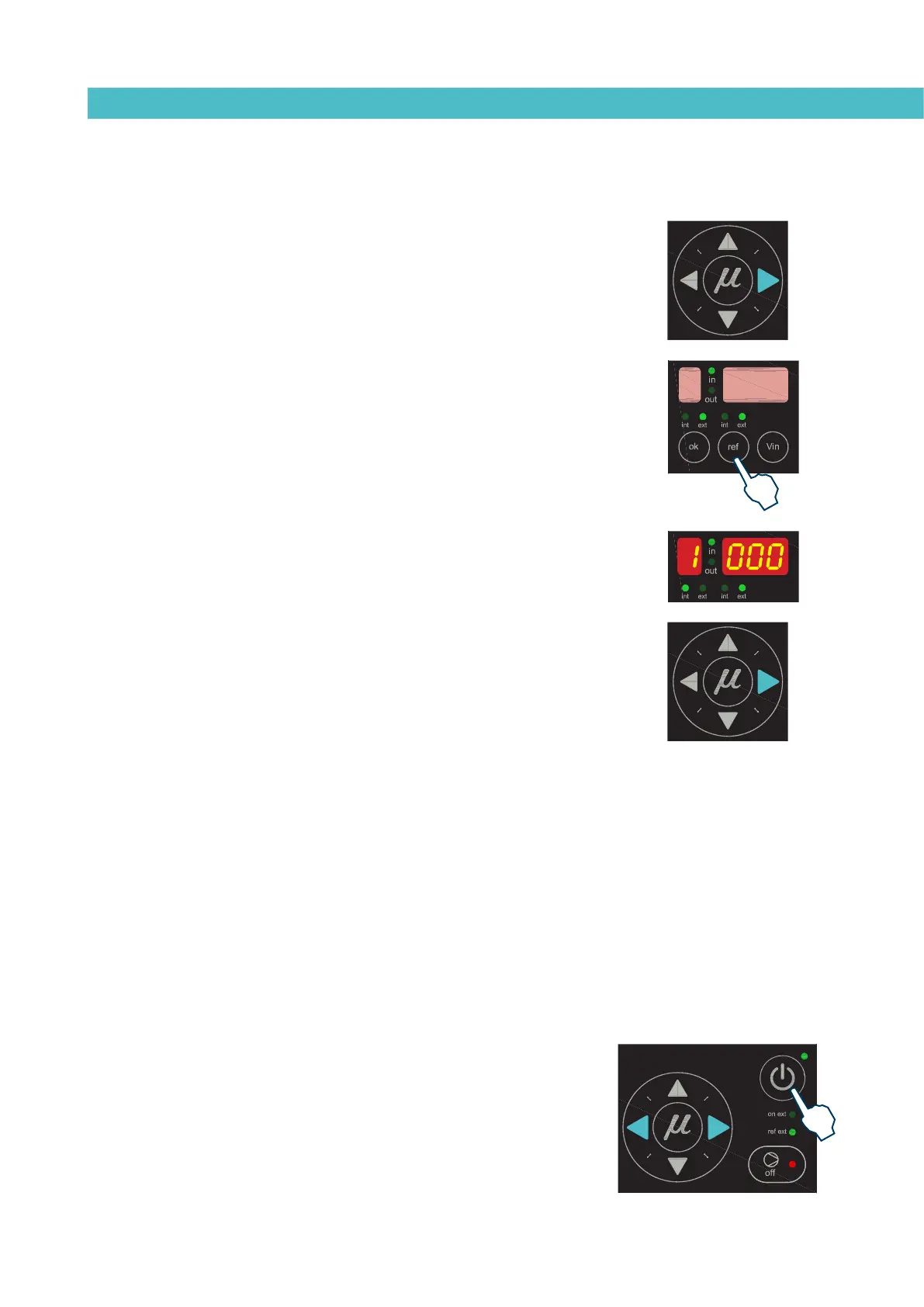
To exit this menu, the equipment must be turned off and started up using the
control card ON/OFF button.
To save the newly entered data, use the right and left arrow keys to go forward
or backward in the menu: if any field has been modified using the up/down
arrow keys, and the ON/ OFF button is pressed to turn the equipment off, the
data will not be saved.