FOCKE MELER GLUING SOLUTIONS INSTALLATION
3-10
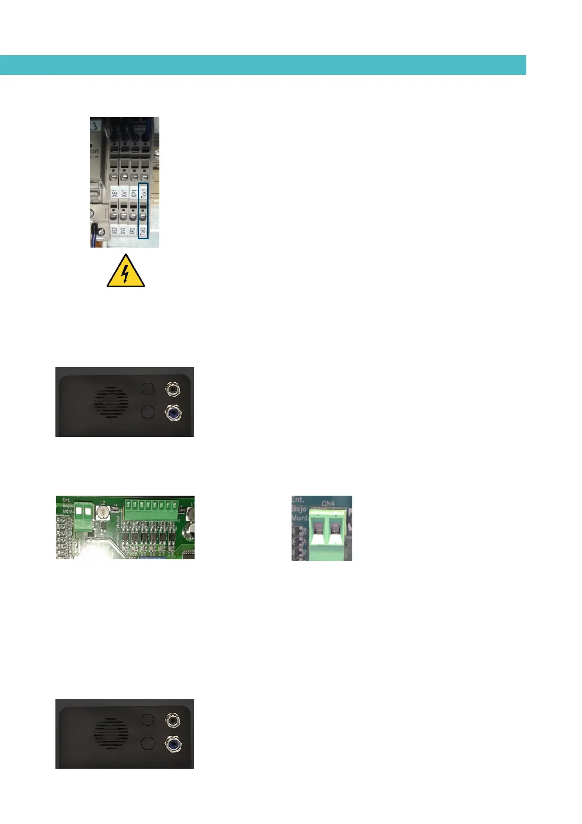
3. Connect the two wires from the start-up signal to the terminals Tok1
and Tok2. This is a double terminal, which makes it necessary to
connect each wire in one of the two holes in the terminal. Since this
contact is not under voltage, there is no connection polarity.
4. Make sure that the cables are firmly attached by the terminal screws.
5. Make sure that the cable is well connected and that its path through
the electrical cabinet presents no risks of snagging, being cut or any
other accidental deterioration.
Warning: It must be connected to 24 AC or DC voltage with a maximum
current of 500mA. If you connect this signal to 230V load current cannot be
less than 50mA.
External standby
1. If this is the only signal being connected, use 0.5 mm
2
two-wire cable.
Install an electrical wall bushing Pg13.5 next to the electrical supply
input.
2. Thread the power cord (max. Ø12.5mm) through the electrical wall
bushing Pg13.5 and fasten it to the inside anchor, making sure that the
cord reaches the control card connector at the position where it will be
installed (CN 4).
3. Remove the connector from the card and connect the two cable wires
to their corresponding connector terminals:
4. Reconnect the card connector.
5. Make sure that the cable is well connected and that its path through
the electrical cabinet presents no risks of snagging, being cut or any
other accidental deterioration.
Low level (optional)
1. If this is the only signal being connected, use 0.5 mm
2
two-wire cable.
Install an electrical wall bushing Pg13.5 next to the electrical supply
input.
contact NO
contact NO