90-826148R2 MARCH 1997 MID-SECTION - 5B-43
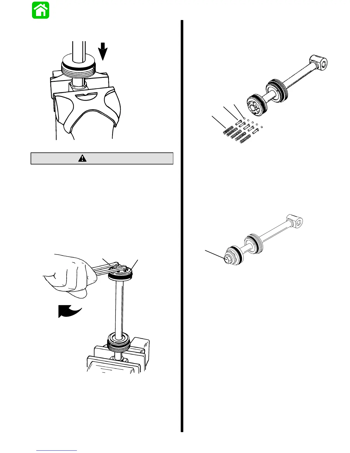
4.Clamp shock rod in soft jawed vise.
5.Position cylinder end cap onto rod as shown.
51146
CAUTION
When installing shock rod piston, spanner
wrench must have1/4 in. x 5/16 in. (6.4mm x8mm)
long pegs to avoid damage to shock rod piston.
6.Apply Loctite Grade “A” (271) to threads on shock
rod.
7.Install shock rod piston.
8.Tighten shock rod piston securely using spanner
wrench (1/4 in. x 5/16 in. long pegs). If a torquing
type spanner tool is used to tighten shock piston,
then torque to 45 lb. ft. (61 N⋅m).
51146
b
a
a-Shock Rod Piston - Torque to 45 lb. ft (61 N⋅m)
b-Spanner Wrench
9.Remove shock rod assembly from vise.
10.Install ball, seat, and spring (five sets) to shock
rod piston.
51147
a
b
c
a-Spring (5)
b-Seat (5)
c-Ball (5)
11.Secure components with shock piston bolt.
Torque bolt to 45 lb.in. (61 Nm).
a
a-Bolt - Torque to 45 lb. ft. (61 N⋅m)

 Loading...