90-826148R2 MARCH 19972A-14 - ELECTRICAL
Principle Of Operation, CDM without
Timing Protection Module (TPM)
The ignition system is alternator-driven with distribu-
tor-less capacitor discharge. Major components of
the ignition system are the flywheel, stator, trigger,
capacitor discharge modules (CDM and spark plugs.
The stator assembly is mounted stationary below the
flywheel and has 3 capacitor charging coils wound in
series. The flywheel is fitted with 6 permanent mag-
nets inside the outer rim. As the flywheel rotates the
permanent magnets pass the capacitor charging
coils causing the coils to produce AC voltage (260 -
320 volts). The AC voltage then is conducted to the
capacitor discharge module (CDM) where it is recti-
fied and stored in a capacitor.
The trigger assembly (also mounted under the fly-
wheel) has 2 coil. The flywheel has another perma-
nent magnet located around the center hub. As the
flywheel rotates, the magnet passes the trigger coil.
This causes the trigger coil to produce a AC voltage
pulse which is sent to an electronic switch (SCR)
within the CDM.
The SCR switch discharges the stored voltage of the
capacitor into the primary side of the CDM’s ignition
coil.
Capacitor voltage within the CDM is amplified as high
as 45000 volts to jump the gap at the spark plug.
The proceeding sequence occurs once-per-engine-
revolution for each cylinder.
Spark timing is changed (advanced/retarded) by ro-
tating the trigger assembly which changes each trig-
ger coil position in relation to the permanent magnets
on the flywheel center hub.
A rev-limiter (over-speed protection) circuit is con-
tained inside the trigger assembly. The trigger
pulse(s) provide power for the rev-limiter circuit, this
circuit in turn counts the trigger pulses to determine
engine RPM. IF the engine RPM increases above
the specified RPM limit, the rev limiter will prevent the
trigger pulses from reaching the CDM eliminating
spark delivery to the cylinder. The Rev limiter will start
to limit at 5900 ± 150 RPM and fully limit at 6200 ± 150
RPM.
Trigger Coil
One Piece assembly, containing two trigger coils-one
for each cylinder located under flywheel. Is charged
by single magnet on flywheel hub. Trigger pulses are
sent to TPM or CDM.
NOTE: Trigger assemblies are different between
TPM and non-TPM systems.
Stator
Located under the flywheel in the stator assembly are
3 charge coils wound in series, they provide voltage
to the capacitor discharge modules (CDM). The
charge coils also provide voltage to power the timing
circuit in the TPM or CDM.
Capacitor Discharge Modules (CDM)
Each module contains an ignition coil and amplifier
circuitry which produces approximately 45000 volts
at the spark plugs.
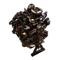
Flywheel
Contains 6 magnets (12 pole) around circumference.
One magnet located on inner hub for trigger. Outer
magnets are for battery charge coils and ignition
charge coils.
NOTE: The inner trigger hub are different be-
tween TPM and non-TPM systems.

 Loading...