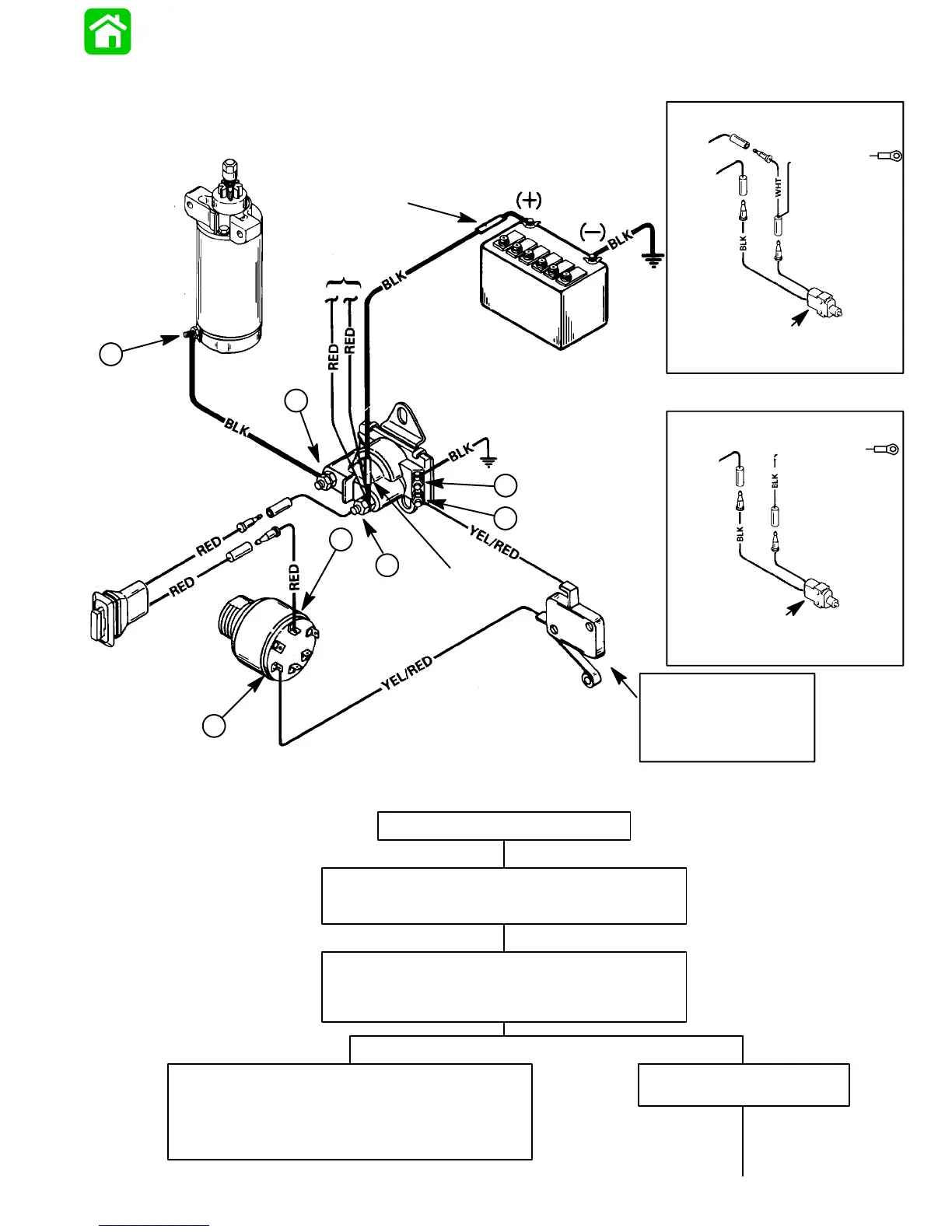
ELECTRIC START TILLER HANDLE
MODEL NEUTRAL START SWITCH
LOCATED ON LOWER ENGINE COWL
TO TPM
TO TPM
ELECTRIC START TILLER HANDLE
MODEL NEUTRAL START SWITCH
LOCATED ON LOWER ENGINE COWL
TO SOLENOID
TO
ENGINE
GROUND
TO SOLENOID
Starter Motor Does Not Turn
SAFETY WARNING: Disconnect BLACK (starter motor)
cable from starter solenoid test point 1 BEFORE making
tests 1-thru-7 to prevent unexpected engine cranking.
TEST 1
Use an ohmmeter (R x 1 scale) and connect meter leads be-
tween NEGATIVE (-) battery post and common powerhead
ground.
No continuity indicated; there is an open circuit in the BLACK
NEGATIVE (-) battery cable between the NEGATIVE (-) battery
post and the powerhead.
• Check cable for loose or corroded connections.
• Check cable for open.
Continuity Indicated
Proceed to TEST 2, on next page.
NEUTRAL START SWITCH
(LOCATED IN CONTROL
HOUSING IF ENGINE IS
EQUIPPED WITH REMOTE
CONTROL)
RED SLEEVE
RED SLEEVE
1
2
3
4
5
6
7
B
C
M
M
A
S
VOLTAGE
REGULATOR
Starting Circuit Troubleshooting Flow Chart
52904
(S/N-0G589999 & Below)
(S/N-0G590000 & Above)
ELECTRICAL - 2B-1190-826148R2 MARCH 1997
The following “STARTING CIRCUIT TROUBLESHOOTING FLOW CHART” is designed as an aid to trouble-
shooting the starting circuit. This flow chart will accurately locate any existing malfunction. Location of “TEST
POINTS” (called out in the chart) are numbered in diagram below.

 Loading...