SECTION - 6 DRIVE SYSTEM AND ENGINE INSTALLATION
90-899883183 DECEMBER 2007 Page 45 / 54
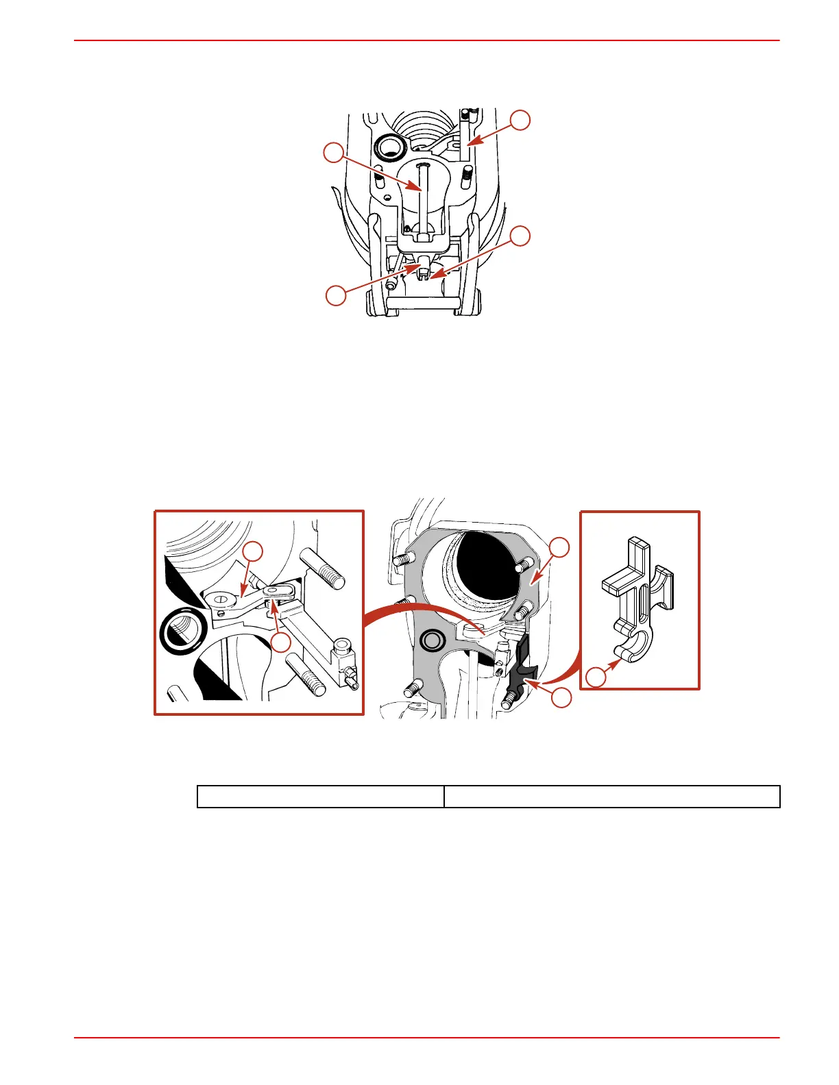
10. Position the bell housing shift shaft coupler so that the slot in the coupler is positioned straight,
fore and aft. Do this by placing remote control shift lever in: forward gear position for RH drives
or reverse gear position for LH drives.
c
a
b
d
7855
a - Shift shaft
b - Shift shaft coupler
c - Shift slide
d - Slot
IMPORTANT: The shift slide assembly is free to rotate on the core wire. Ensure that the shift slide
remains in an upright position and is properly engaged with the shift shaft lever roller while installing
the drive unit.
11. Engage the shift shaft roller into the shift shaft lever.
12. Place the gasket on the bell housing.
13. The shift shaft slide stabilizer tool is installed on the stud directly below the shift slide.
a
b
7859
c
c
d
a - Shift shaft lever
b - Roller
c - Shift shaft slide stabilizer tool
d - Gasket
Shift Slide Stabilizer 91‑865232

 Loading...
