MI 3152(H) EurotestXC (2,5 kV) Tests and measurements
117
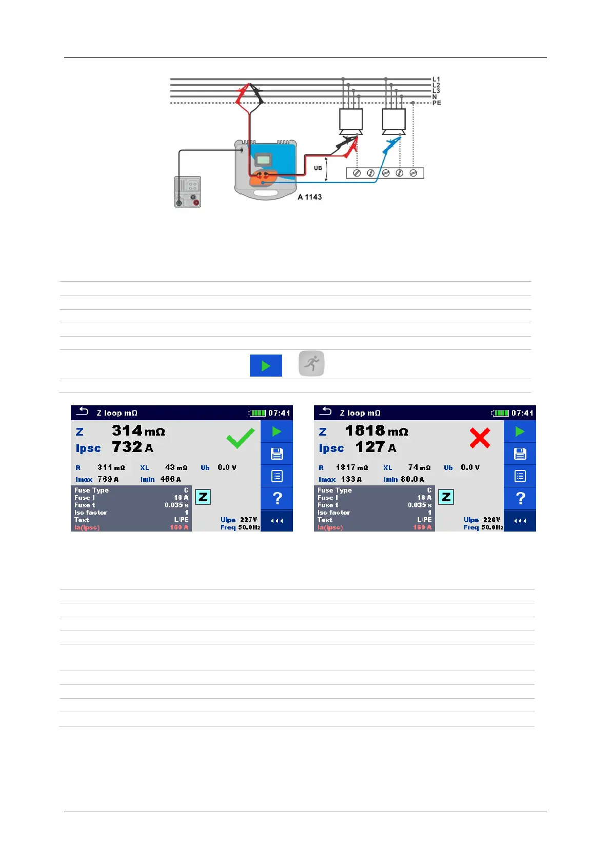
Figure 7.40: Contact voltage measurement – Connection of A 1143
Measurement procedure
Enter the Z loop m function.
Set test parameters / limits.
Connect test leads to A 1143 – Euro Z 290 A adapter and switch it on.
Connect A 1143 – Euro Z 290 A adapter to the instrument using RS232-PS/2 cable.
Connect test leads to the object under test, see Figure 7.39 and Figure 7.40.
Start the measurement using or button.
Save results (optional).
Figure 7.41: Examples of high precision Loop impedance measurement result
Measurement results / sub-results
Standard prospective fault current
Maximal prospective fault current
Minimal prospective fault current
Contact voltage at maximal prospective fault current (contact voltage measured
against Probe S if used)
Resistance of loop impedance
Reactance of loop impedance

 Loading...