MI 3152(H) EurotestXC (2,5 kV) Tests and measurements
156
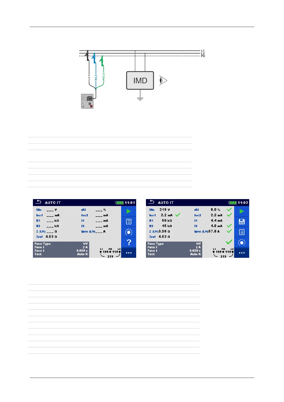
Connection diagram
Figure 7.94: AUTO IT measurement
Measurement procedure
Enter the AUTO IT function.
Set test parameters / limits.
Measure the impedance Zref at origin (optional), see chapter
7.14 Voltage Drop.
Connect test cable to the instrument.
Connect test leads to the object under test, see Figure 7.94.
Save results (optional).
Figure 7.95: Examples of AUTO IT measurement results
Measurement results / sub-results
Voltage between phases L1 and L2
First fault leakage current at single fault between L1/PE
First fault leakage current at single fault between L2/PE
Threshold insulation resistance between L1-PE
Threshold insulation resistance between L2-PE
Calculated first fault leakage current for R1
Calculated first fault leakage current for R2
Prospective short-circuit current

 Loading...