© Microhard Systems Inc. 20
3.0 Hardware Features
3.1.3 Connectors and Indicators
3.1.3.1 Front & Top
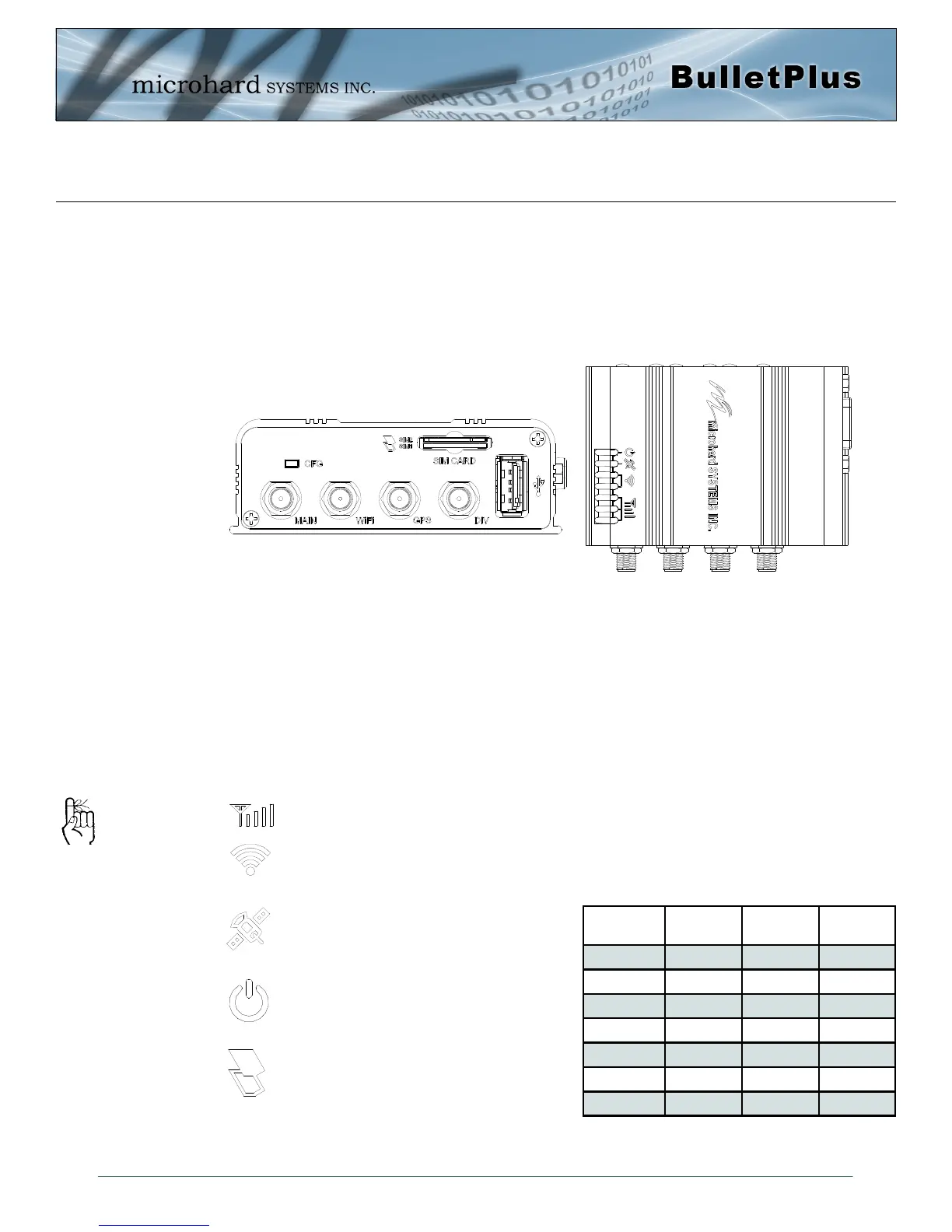
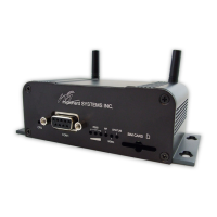
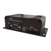
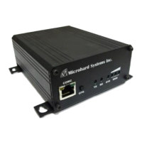
On the front of the Bullet is the CFG Button, USB Port, Main, GPS & Diversity, GPS & WIFI Antenna
Connectors and SIM Card Slot. The top of the Bullet are the status indicators, RSSI, Tx, RX, GPS and
PWR.
The USB port is a future development to be available in later releases of firmware.
CFG (Button) - Holding this button while powering-up the Bullet will boot the unit into FLASH FILE SYS-
TEM RECOVERY mode. The default IP address for system recovery (only - not for normal access to the
unit) is static: 192.168.1.39. Hold for 1 second for httpd recovery mode, 5 seconds for tftp recovery mode,
or 10 seconds for master reset. If button is held for longer than 15 seconds the button will be ignored.
If the unit has been powered-up for some time (>1 minute), depressing the CFG Button for ~10 seconds
(unit will reboot) will result in FACTORY DEFAULTS being restored, including the static factory IP address.
This IP address is useable in a Web Browser for accessing the Web User Interface.
Receive Signal Strength Indicator (RSSI) - As the received signal strength increases, starting
with the furthest left, the number of active RSSI LEDs increases.
Tx(Red)/Rx(Green) LED’s - The Tx/Rx LED’s indicate carrier (cellular) traffic.
Drawing 3-6: Bullet Front & Top View
Signal
(dBm)
RSSI1 RSSI2 RSSI3
(-85, 0] ON ON ON
(-90, -85] ON ON FLASH
(-95, -90] ON ON OFF
(-100, -95] ON FLASH OFF
(-105, -100] ON OFF OFF
(-109, -105] FLASH OFF OFF
Other SCANNING SCANNING SCANNING
GPS - Indicates that the optional standalone
GPS module has synchronized and is ready
for use.
PWR LED - The Power LED indicates that
power has been applied to the module.
Flashing indicates a bootup process.
SIM Card - This slot is used to install SIM
card(s) provided by the cellular carrier. Ensure
that the SIM card is installed properly by pay-
ing attention to the diagram printed next the
SIM card slot. The Bottom slot is SIM1, the contact
should face down, and the notch should be to the
right.
The factory default network
settings:
IP: 192.168.168.1
Subnet: 255.255.255.0
Gateway: 192.168.168.1
Table 3-1: RSSI LED’s