© Microhard Systems Inc. 21
3.0 Hardware Features
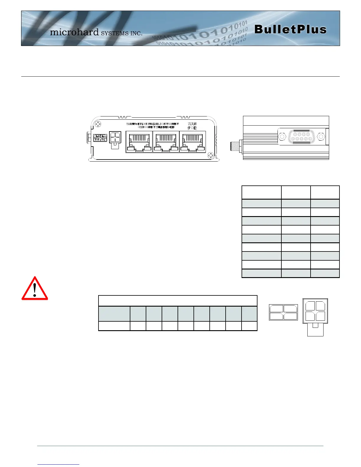
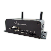
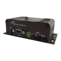
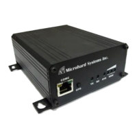
Drawing 3-7: BulletPlus Rear & Side View
The Data Port (RS232 DCE) on the side of the unit is used for
RS232 Serial Data based field devices at 300 bps to 921kbps.
The Ethernet Ports (2LAN/WAN) are 10/100 Mbps RJ-45
interfaces used to connect devices Ethernet based field devices.
Programmable I/O– The Bullet has 2 programmable Analog/
Digital Inputs or 2 Digital Outputs. Maximum recommended load
for the output pin is 150mA @ 30 Vdc (Vin).
Vin+/Vin– is used to power the unit. The input Voltage range is
7-30 Vdc.
PoE– The Bullet can also be powered using Passive PoE on the
Ethernet Port (WAN), via a PoE injector.
3.1.3.2 Rear & Side View
On the side of the Bullet is the Data Port (RS232) and on the back are the Power and Ethernet(PoE)
interfaces and the 2x Programmable I/O.
Caution: Using a power
supply that does not
provide proper voltage
may damage the modem.
Ethernet RJ45 Connector Pin Number
Source
Voltage
1 2 3 4 5 6 7 8
9 - 30 Vdc Data Data Data DC+ DC+ Data DC- DC-
Table 3-3: Ethernet PoE Connections
Name Data Port Input or
Output
DCD 1 O
RXD 2 O
TXD 3 I
DTR 4 I
SG 5
DSR 6 O
RTS 7 I
CTS 8 O
RING 9 O
Table 3-2: Data RS232 Pin Assignment