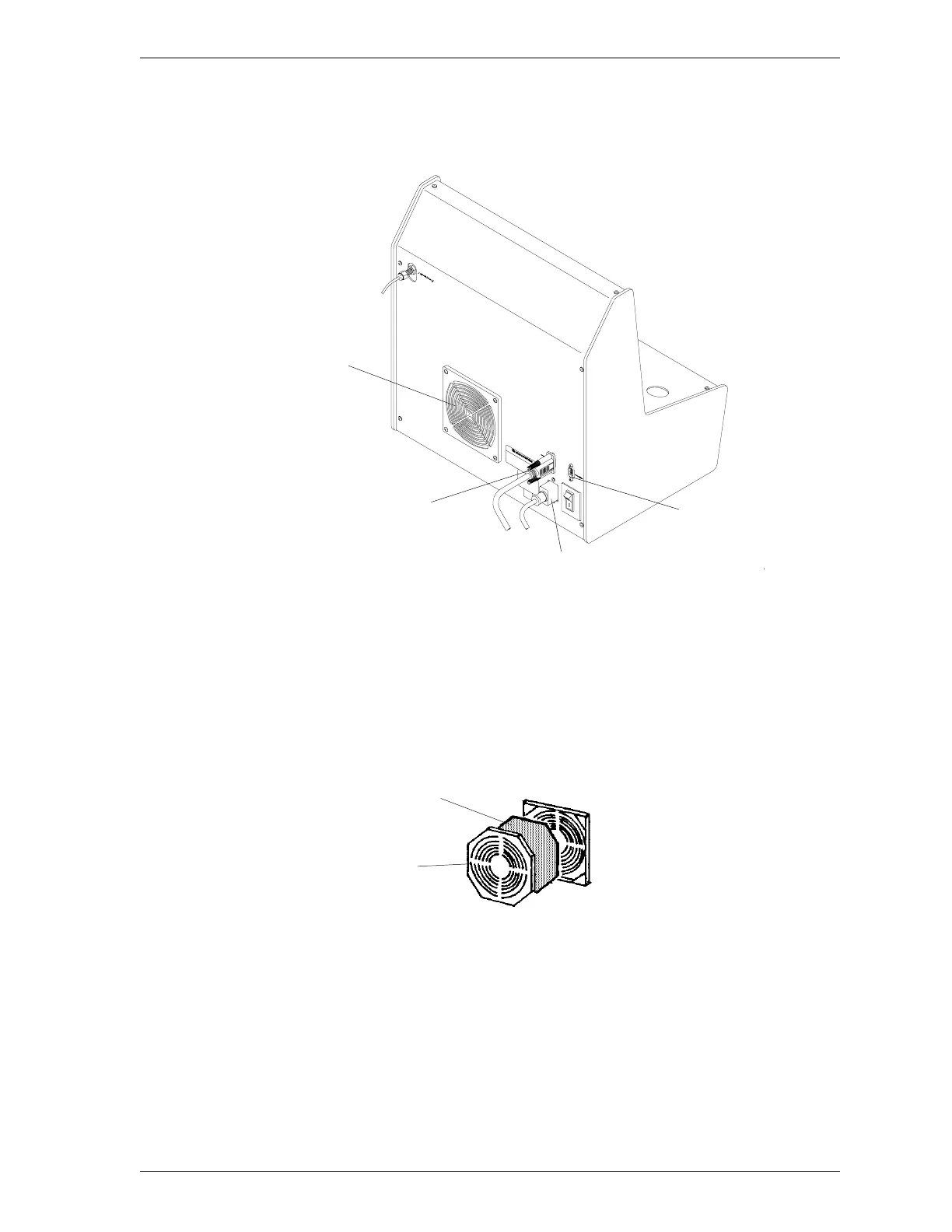
12. Connect the cable from the control module to the left (data-in) connector of
the first SmartPrep and tighten the retaining screws.
Figure 1-4. Connecting Cables to the Rear Panel
13. If you wish to connect an additional SmartPrep, connect one end of the ca-
ble to the right (data-out) connector and the other end of the cable to the
left (data-in) connector of the next SmartPrep. You may connect up to four
SmartPreps in this manner.
14. Install the power supply filter as follows:
a. Insert the tip of a flat-head screwdriver (or similar object) into the grill
of the retainer and gently pull outward. DO NOT remove the screws on
the plate holding the filter.
b. Insert one of the filters supplied in the SmartPrep kit.
c. Replace the retainer.
Filter
Retainer
Data-Out Connector
(Next SmartPrep)
Data-In Connector
(Control Module or
previous SmartPrep)
Power Cord Connector
Power Supply Filter
SmartPrep Installation
Sep 98 1-7