302 Chapter 31: Outputs
PRO6 Live Audio System
Owner’s Manual
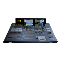
Output channel ID (GUI only)
You can change the channel name in the GUI
channel strip. This can be done in the output
channel overview or in any of the processing areas.
To change the background colour of the output channel name field (green in the
example shown), open the Output Channels Sheet screen of the GUI menu.
>> To change the channel name in the GUI channel strip
Click within the channel name field and type in the new channel name (see “Text
editing” on page 45).
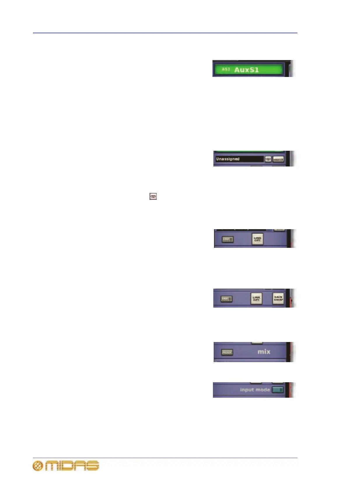
Output channel source/destination (GUI only)
The channel’s destination is shown in the text field
of the configuration processing area. If no
destination has been selected, it will contain the
text “Unassigned” (as shown right). You can select the destination for this channel by
clicking dest, which opens the Patching screen (see Chapter 8 "Patching" on page 55).
For routing information, see Table 22 “Navigating to the Patching screen” on page 376.
By clicking the recorder button (returns only) you can set the input source to tape
returns.
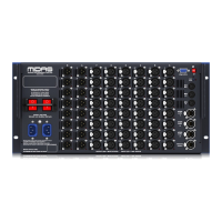
Stereo linking (GUI only)
The linking section of the configuration processing
area has a LINK switch for linking the selected
output channel to the adjacent (higher numbered)
output channel. The LINK OPT. button opens a
Stereo Linking Options window from where you can select which parameters you
want to link. For more information, see “Stereo linking” on page 307.
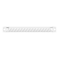
Gain swap (GUI only)
Only return has the gain swap facility. Clicking
GAIN SWAP swaps from remote (stage box) gain
to digital trim (console gain), and vice versa. For
more information, see “Mic amp input gain
(preliminary input processing)” on page 264.
Mix mode (GUI only)
The mix section (aux only) has a MODE button for
scrolling through the three mix modes, that is, mix,
mix minus and group.
Input mode (GUI only)
The button in the input mode section (return only)
time aligns the return channel with the input
channels.