bands are spaced 1/3 octave apart on the standard ISO 266 frequency centres. All the
same as the input.
filters. Each filter is adjusted via a control knob on the GUI screen.
GEQ) or the individual filter switch.
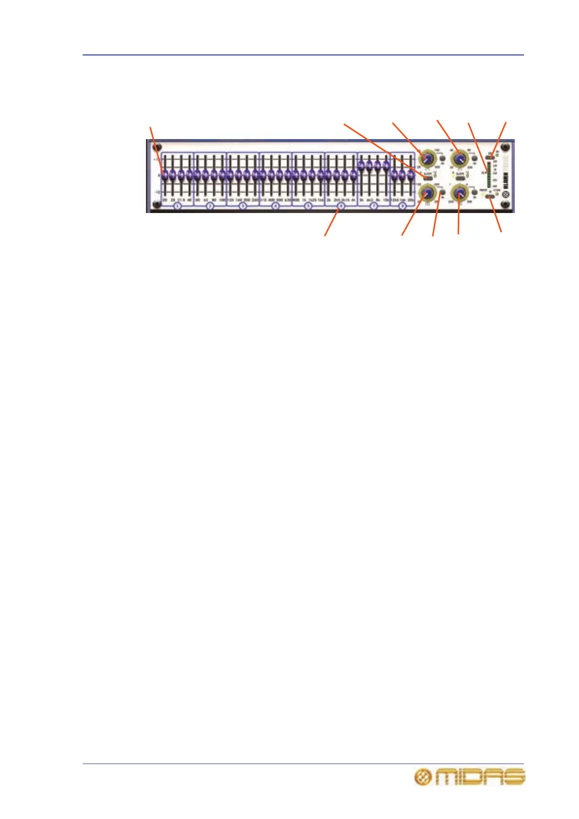
1 Fader (31-off).
2 SLOPE button for switching the high or
low pass filter between 6dB and 12dB.
Adjacent yellow LEDs indicate the active band.
3 Low pass filter control knob for adjusting
the cut off frequency, which is continuously
variable from 20Hz to 500Hz.
4 High pass filter control knob for adjusting
the cut off frequency, which is continuously
variable from 2kHz to 20kHz.
5 EQ button for selecting EQ. The adjacent
green IN LED shows the EQ is on (illuminated)
or is being bypassed (extinguished).
6 10-segment meter, shows the incoming
signal level and is pre-EQ (but post-gain
control). Clipping is post-EQ (and post-gain
control), such that internal clipping due to
excessive EQ, that is, if a high input level is
further boosted by the use of EQ, will also be
shown. The LED functions are: two red LEDs
illuminate when signal has exceeded +20dBu
and is being clipped; two yellow LEDs
illuminate when signal level exceeds 0dB
(range is between 0dB to +20dB); and the top
five green LEDs encompass the signal level
range of between 0dB and -40dB, while the
bottom one illuminates when the signal has
exceeded -40dB.
7 Q button for selecting proportional Q
(PROP.) or constant Q (CON.) modes.
8 Notch filter control knob for adjusting the
position of the notch filter within the range
20Hz to 20kHz.
9 IN button for switching the respective
high pass/low pass/notch filter in/out.
10 Notch filter control knob for adjusting the
position of the notch filter within the range
200Hz to 2kHz.
11 Show the view number and section of the
GEQ front panel associated with the assignable
controls (I zone).
1
2
3
4
5
8
6
7
11
9
10