564 Appendix P: Parameters Copied Through Scenes
XL8 Live Performance System
Owner’s Manual
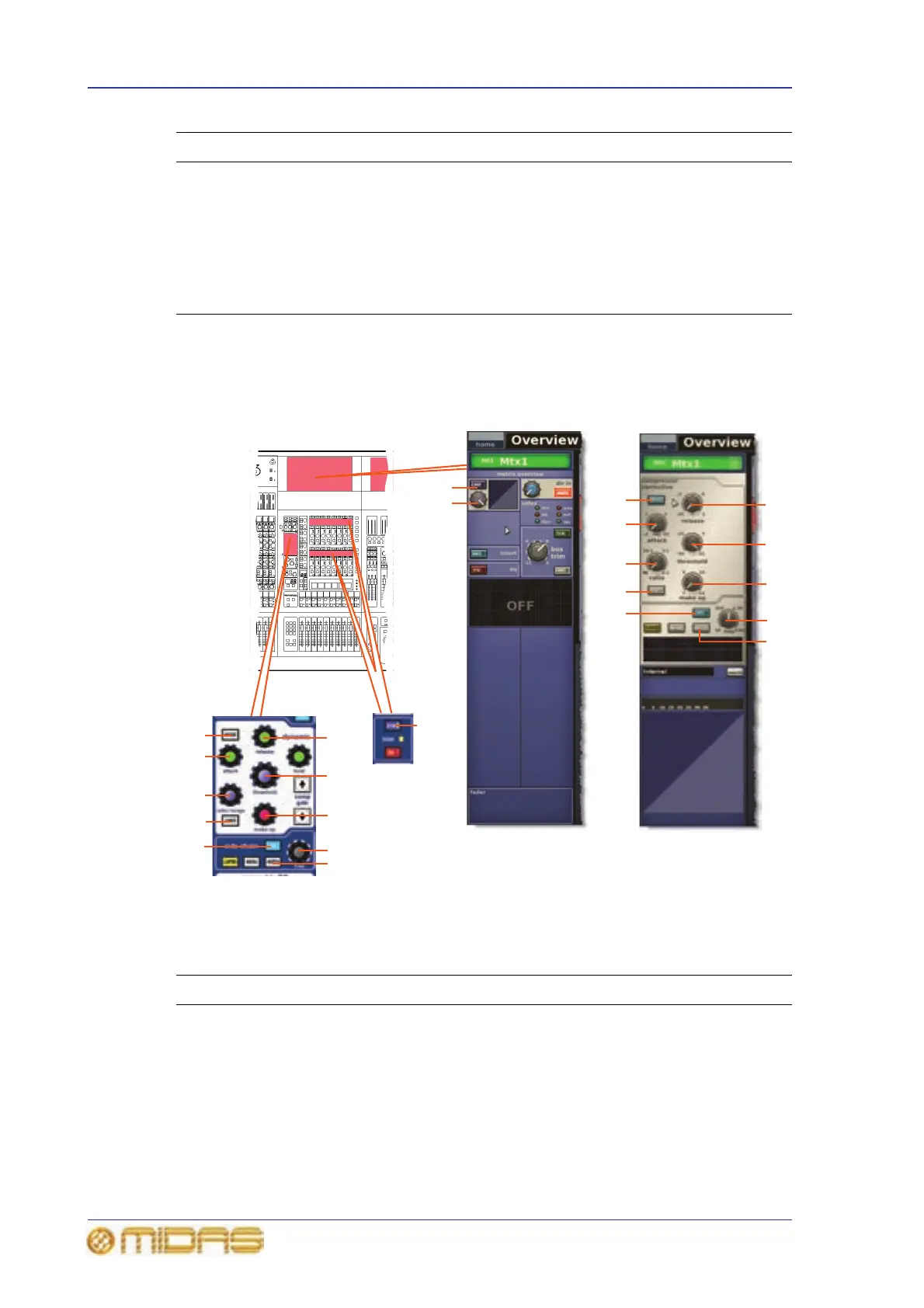
Comp./Output Dyn
The following diagram shows the parameters of the compressor processing area copied
through scenes.
Note: Only the corrective compressor is shown above, but this is typically the same for
the other compressor modes (adaptive, creative, vintage and shimmer).
10 Delay field Delay in milliseconds (ms) and metres (m)
11 delay control knob Delay level
12 C/O switch
Order of processing: Dyn.
JIns.JEQ or
EQ
JIns.JDyn.
13 Graphic Order of processing
14 Field Direct input source
Item Control Parameter
1 DYN/[CMP] switch Compressor on/off
2 release control knob Compressor release
3 threshold control
knob
Compressor threshold
4 KNEE pushbutton Compressor knee: hard, medium or soft
5 IN switch Compressor sidechain in/out
6 freq control knob Compressor sidechain frequency
Item Control Parameter
Compressor
processing area in
GUI channel strip
3
11
6
7
2
10
9
8
10
9
8
4
3
11
2
5
6
7
1
3
aux send
overview in GUI
channel strip
5
4
1