6-45
6.7 Remote Display Box
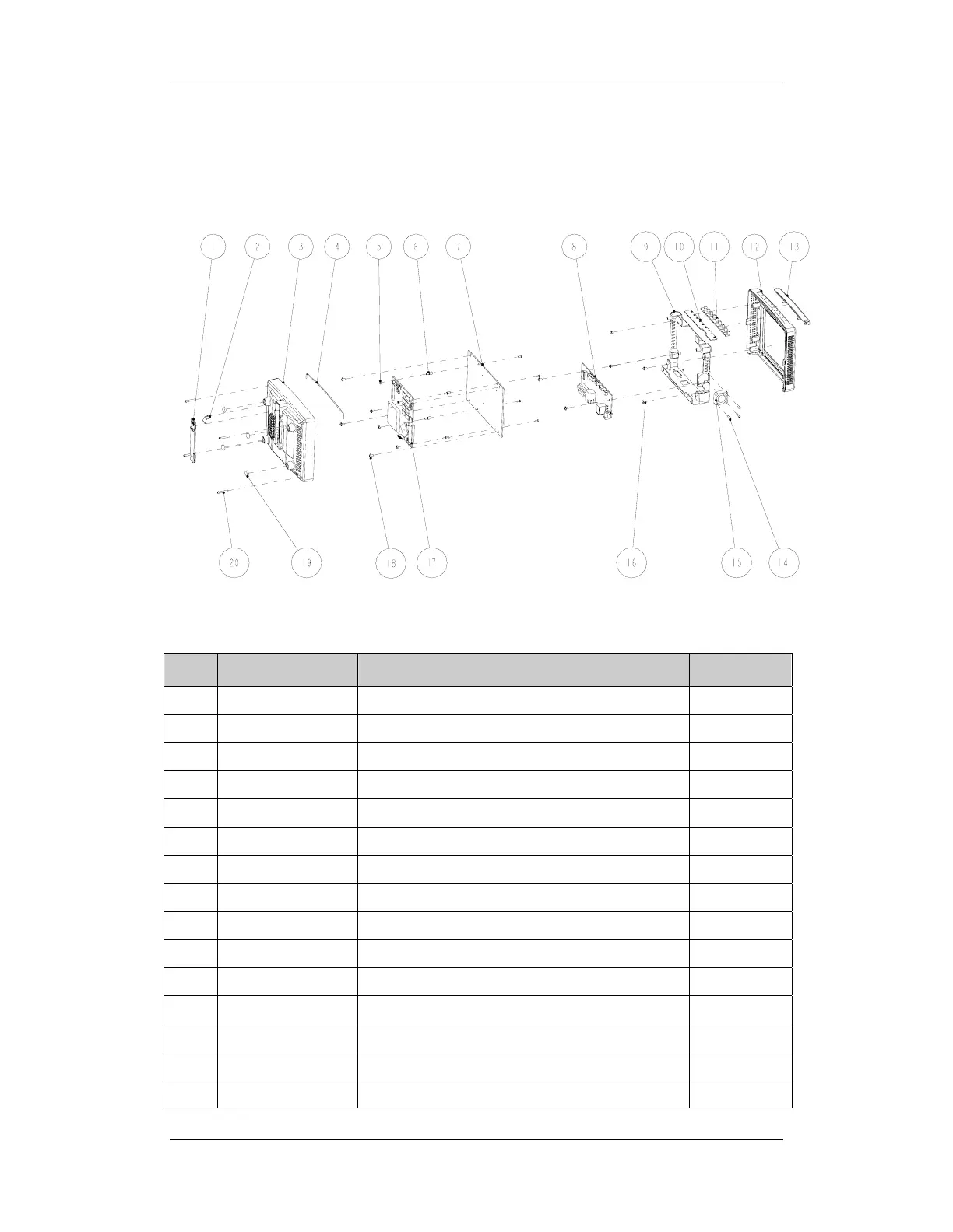
Exploded View
Part List
SN P/N Description Qty
1 M12A-20-75103 CIS lock catch 1
2 M12A-20-75107 Lock catch spring 1
3
M12A-21-75110
CIS bottom housing 1
4 M6G-020015--- Silicone tube 1
5 M04-011001--- Hex nut GB/T6170-2000M2.5 4
6 M04-060021--- Stud screw M2.5×7+6-6 4
7 M11A-30-75026 Remote display mother board 1
8 M11A-30-75000 Equipment interface board 1
9 M11A-20-75004-51 Remote display box rack 1
10 M12A-30-75002 Indicator board 1
11 M12A-20-75106 Light block 1
12 M12A-20-75101-51 CIS top housing 1
13 M12A-20-75102-52 Remote display box light cover 1
14 M04-004705--- Cross pan head screw M2.5×12 3
15 6800-20-50164 Module fan and cable 1