2-4
2.3 Main Unit
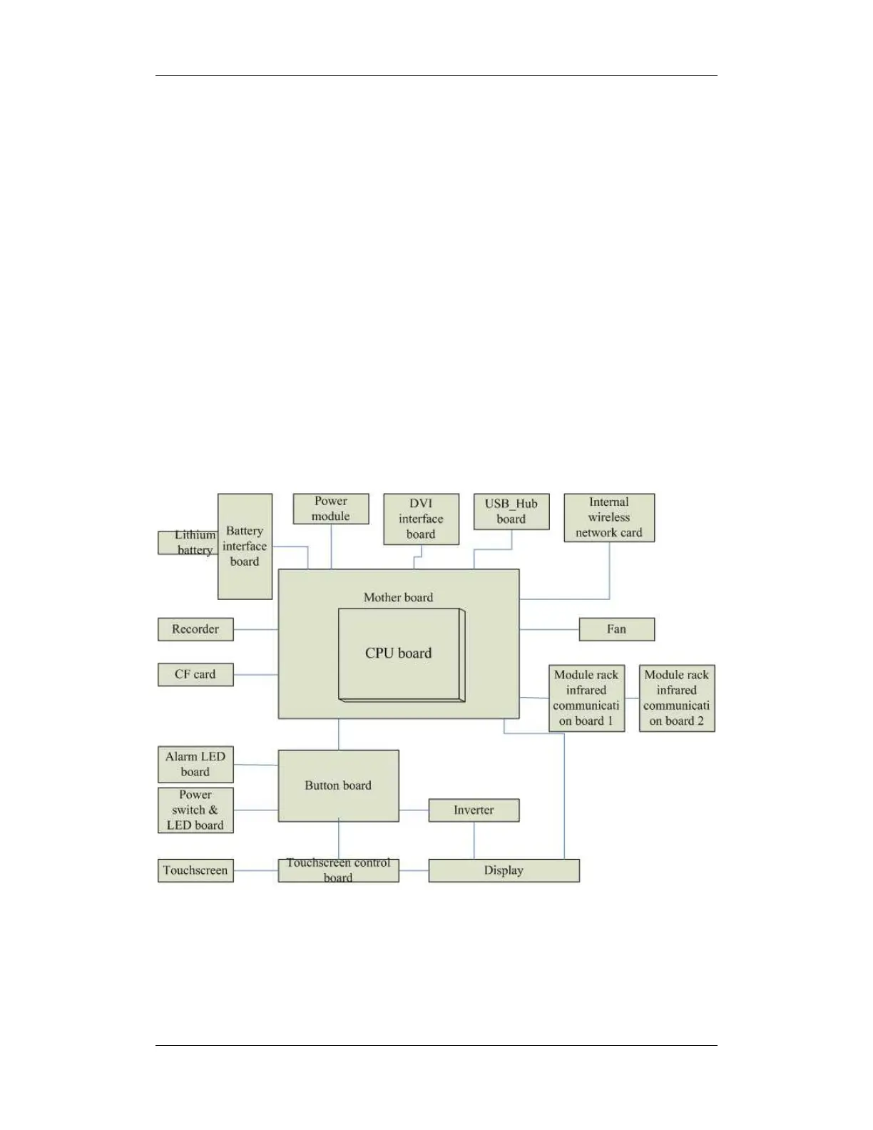
The patient monitor consists of:
Input system: button board, knob, touchscreen, power switch and LED board
Output system: LCD panel, alarm LED board, recorder and speaker
Processing and communications system: main board and integral module rack assembly.
Power management system: battery, battery interface board and power module
Equipment interface system: USB_Hub interface board, DVI interface board CF card
assembly and internal wireless network card.
Additionally, the patient monitor can also connect a satellite module rack (SMR), parameter
modules, mouse, keyboard, etc.
The following diagram illustrates the structure of the patient monitor