2-5
2.3.1 Input System
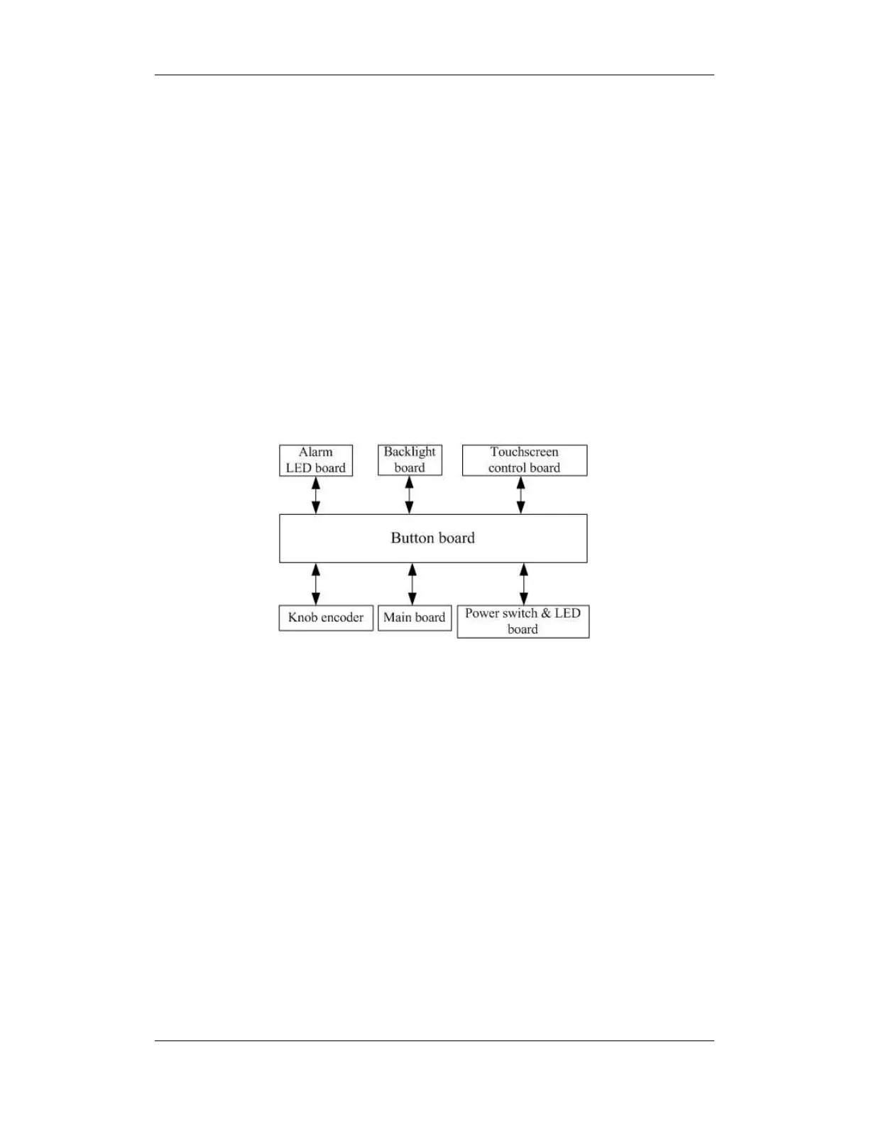
Button board
The button board, located at the lower part of the monitor’s front panel, contains 6 keys and
provides connections for the following components to the main board:
Knob
Power switch & LED board
Touchscreen control board
Alarm LED board
Inverter
The following diagram shows the button board connections.
Knob
The knob can be pressed, or rotated both clockwise and counter-clockwise. It is connected
with the button board.
Touchscreen
The touchscreen enables touch operations and can be calibrated. It is connected with the
touchscreen control board and main board.
Power switch & LED Board
The power switch & LED board controls the power supply for the main unit. It has three
LEDs, which respectively indicate the AC power status, battery status and monitor power
on/off status. It is connected with the button board.