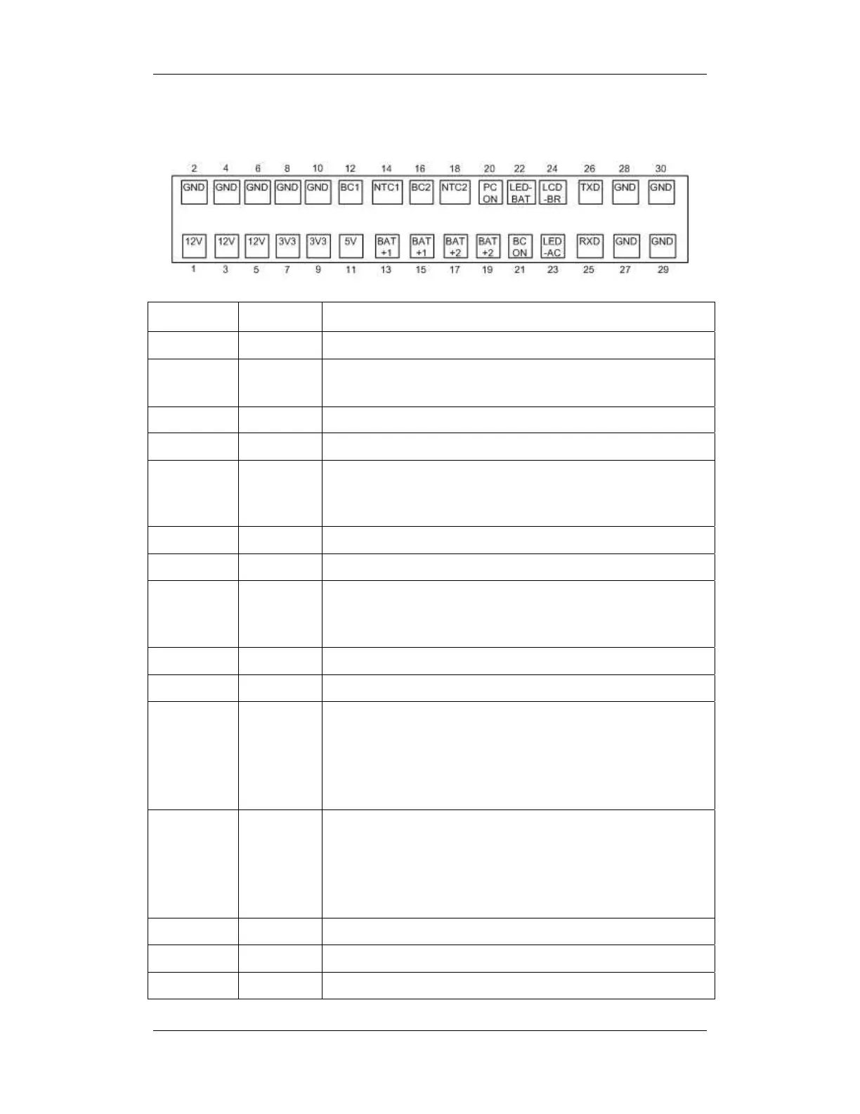
2-11
The following diagram shows the pins of the power socket connecting the power module and
the mother board:
Pin ID Marking Description
1/3/5 12V The positive output of the 12 VDC power
2/4/6/8/10/
27/28/29/30
GND The output grounding terminal of the power board.
7/9 3V3 The positive output of the 3.3 VDC power
11 5V The positive output of the 5 VDC power
12 BC1 Signal indicating whether battery 1 is available. Low level indicates
that battery 1 is available and high level indicates that battery 1 is
not available.
13/15 BAT+1 Input of battery 1, connecting to the positive pole of the battery.
14 NTC1 Thermistor signal of battery 1.
16 BC2 Signal indicating whether battery 2 is available. Low level indicates
that battery 2 is available and high level indicates that battery 2 is
not available.
18 NTC2 Thermistor signal of battery 2.
17/19 BAT+2 Input of battery 2, connecting to the positive pole of the battery.
20 PCON Power on/off control signal. It is a TTL pulse signal inputted from
the back board. Every time when the power on/off switch is pressed
(pulse of falling edge), a switch between power “on” and “off”
happens. The pulse duration is no less than 0.1 s for power on, 2 s
for power off and 10 s for illegal power off.
21 BCON Backlight on/off signal and switch output signal. The main board
sends the LCD backlight on/off signals to the power board via a
serial port, the power board processes the signals and output them.
Low level is output when the backlight is off and high level is
output when the backlight is on.
22 LED-BAT Battery status indication driving output
23 LED-AC AC power status indication signal
24 LCD-BR Backlight brightness control voltage.