88
1
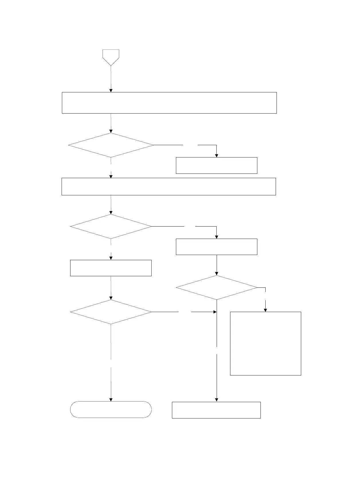
① Remove the connecting cable for strain gage applied transducer from the terminal board.
② Measure the voltage between the A and C connectors.
※ Set the connecting range to DC・V for the measuring instrument such as tester and so on.
The voltage between
A and C is DC5 V in stable
condition.
① Connect the connecting cable for strain gage applied transducer to the terminal board again.
② Confirm the output voltage of the load cell according to the paragraph 10-5.
Monitoring display
exceeds the range from –2.5
mV/V to 2.5 mV/V.
Make re-calibration according
to the procedures in chapter 4.
Same condition
Start measurement
YES
NO
NO
Contact with Minebea.
NO
Shorten between B and D in the
connector.
YES
Monitoring display
exceeds the range from –2.5 mV/V
o 2.5 mV
V.
YES
YES
Following causes can be
considered
① The input of strain gage applied
transducer exceeds the range
from -2.5 mV/V to 2.5 mV/V.
② The strain gage applied
transducer has broken due to
overload and so on.
③ The signal wire of the strain
gage applied transducer has
been cut off.
NO
Inform Minebea about the contents of
failure and situation at site in details.