8. Safety-related functions and interfaces
MiR250 Dynamic Integrator Manual (en) 09/2023 - v.2.1 ©Copyright 2020–2023: Mobile Industrial Robots A/S. 92
Pins 2 in interfaces Aand B of the Auxiliary safety functions are used for the Safeguarded stop
function.
Locomotion
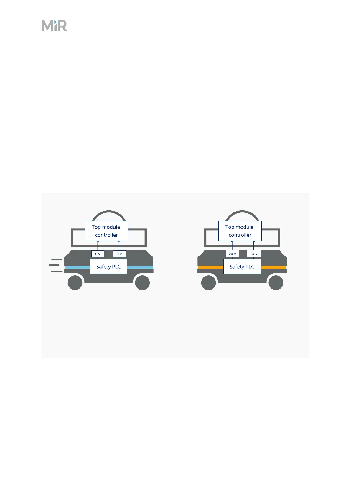
The Locomotion function indicates to the top module safety device when the robot is moving. Use
this function to ensure that the top module is not powered while the robot is driving.
This function uses two output pins, where both pins deliver 0 Vwhen the robot is driving and 24 V
when the robot is stopped. You can use this interface to make your top module behave
differently depending on whether the robot is driving or not.
The interface is intended to be used to program the top module to go into a safe state when the
robot is driving. For example, by engaging the brakes in any actuators that may result in injury to
personnel.
Robot is driving
When the robot is driving, the safety PLC
sends a 0 V signal to the top module
through the Auxiliary safety function
interface.
Robot is at standstill
When the robot is stopped, the signal
becomes 24V.
Pins 5 in interfaces Aand B of the Auxiliary safety functions are used for the Locomotion function.