11. Electrical interfaces
MiR250 Dynamic Integrator Manual (en) 09/2023 - v.2.1 ©Copyright 2020–2023: Mobile Industrial Robots A/S. 113
11.2 Right side interfaces
This section describes the general purpose interfaces located in the right side compartment on
top of MiR250 Dynamic.
GPIO A and B
The GPIO has the following pins:
l
Four inputs, for use with 24V, but robust against 48V.
l
Four outputs, for use with 24V.
The GPIO supports low current/power devices like relays, contactors, lamps, and separate PLC
units.
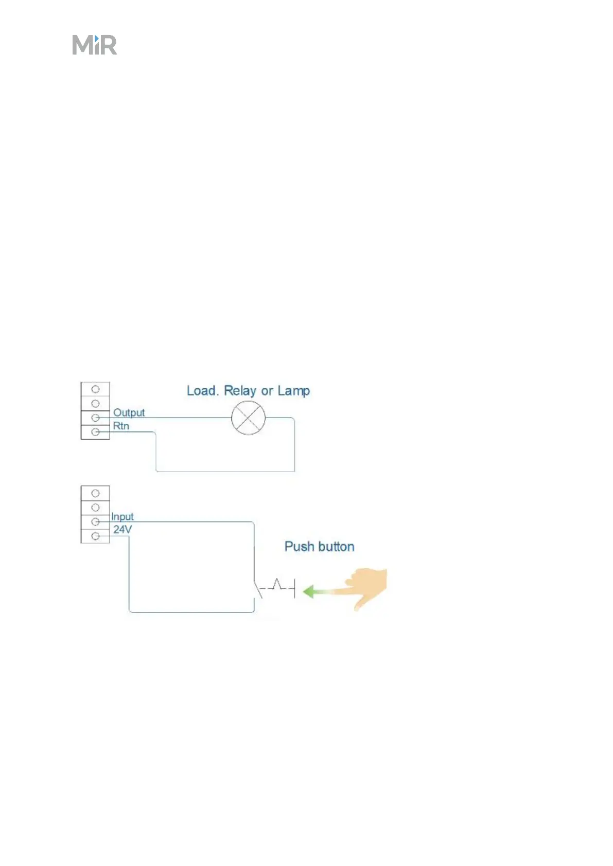
Figure 11.4 Outputs and RTNs are used to send signals to the top module, and inputs and 24V pins are
used to receive signals from the top module
To use the GPIO for a top module of your own design, ensure that the Shelf feature is disabled
under System >Settings >Features. This enables the GPIO interface to work as input and
output to top modules that can be controlled in missions. The shelf feature uses a different kind
of communication that is specific to the MiR top modules.