11. Electrical interfaces
MiR250 Dynamic Integrator Manual (en) 09/2023 - v.2.1 ©Copyright 2020–2023: Mobile Industrial Robots A/S. 114
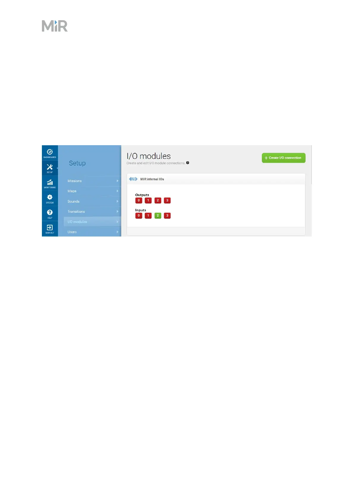
Outputs (O0, O1, O2, O3) can be toggled on and off by the robot in a Set I/Omodule mission
action or manually in Setup >I/O modules.
A top module can be connected to the output pins and monitor when they are active at 24V. RTN
is used as ground.
Inputs (I0, I1, I2, I3) can be used by the top application to send inputs to the robot. When 24V is
connected to the input pin, the robot registers the input as active.
Figure 11.5 Example of I2 registered as high by the robot
Output pins must be connected to RTN pins, and input pins must be connected to 24V pins.
 Loading...