6 HK-KT SERIES
6.8 Dimensions
137
6
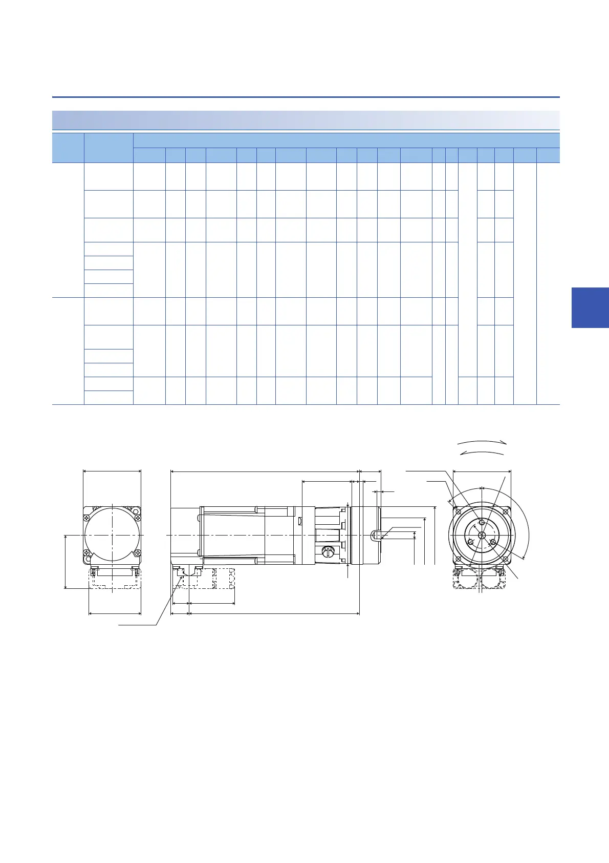
With flange-output type gear reducer for high precision
applications, flange mounting
HK-KT053(B)G5/HK-KT13(B)G5
*1 The values in ( ) of the dimensions are for the servo motors with an electromagnetic brake.
[Unit: mm]
Model Reduction
ratio
Variable dimensions
*1
L LA LB LC LD LE LF LG LH LK LM KL T N P R M KA LT
HK-
KT053(
B)G5
1/5
(40)
95
(130)
46 18 40 24 2.5 5 34.5 82.3
(117.3)
3 3 M4 6 3.4 36.8 12.7
1/5
(60)
119.5
(154.5)
70 30 60 40 3 8 56 106.8
(141.8)
56 7 5.5
1/9 95
(130)
46 18 40 24 2.5 5 34.5 82.3
(117.3)
33 6 3.4
1/11 119.5
(154.5)
70 30 60 40 3 8 56 106.8
(141.8)
56 7 5.5
1/21
1/33
1/45
HK-
KT13(
B)G5
1/5
(40)
107.5
(142.5)
46 18 40 24 2.5 5 34.5 94.8
(129.8)
33 6 3.4
1/5
(60)
132
(167)
70 30 60 40 3 8 56 119.3
(154.3)
56 7 5.5
1/11
1/21
1/33 134.5
(169.5)
105 45 90 59 8 10 56.5 121.8
(156.8)
M6 10 9
1/45
5
+0.012
0
14
+0.018
0
5
+0.012
0
14
+0.018
0
14
+0.018
0
24
+0.021
0
L
31.5
KA
36
11.5
LT
0.5X40°
4-M
117.3
LG
LH
T
LK
LM
LD
45°
39
LF
LE
LC
KC
120°
LA
LB
N-P screw hole
depth R
Connector
Rotation direction
Under reverse rotation command
Under forward rotation command
 Loading...


