50
4 CONNECTING THE SERVO AMPLIFIER AND ROTARY SERVO MOTOR
4.2 Wiring
HK-ST/HK-RT (3.5 kW - 7.0 kW) series
Refer to the following for the wires used for wiring.
Page 55 Selection example of wires
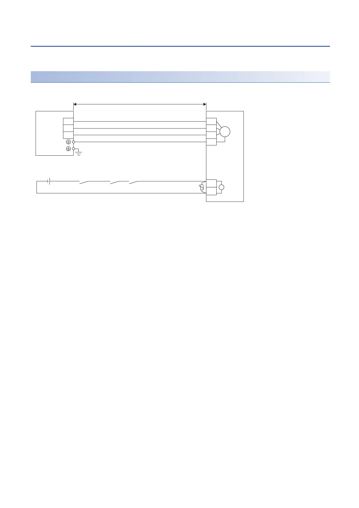
Wiring diagram
■Connecting with MR-J5 1-axis servo amplifier
*1 The electromagnetic brake terminals (B1 and B2) have no polarity.
*2 Do not use the 24 V DC interface power supply for the electromagnetic brake.
*3 Configure a circuit which interlocks with an emergency stop switch to shut off.
*4 Some rotary servo motors do not have an electromagnetic brake. Refer to chapters 6 and 7.
MBR
ALM
U
V
W
RA3
*3
B1
B2
U
V
W
E
RA1RA2
M
B
*1 *4
U
CNP3
50 m or shorter
Rotary servo motor
Servo amplifier
(Electromagnetic
brake interlock)
24 V DC power
supply for
electromagnetic
brake
*2
(Malfunction)
 Loading...


