7 HK-ST SERIES
7.8 Dimensions
183
7
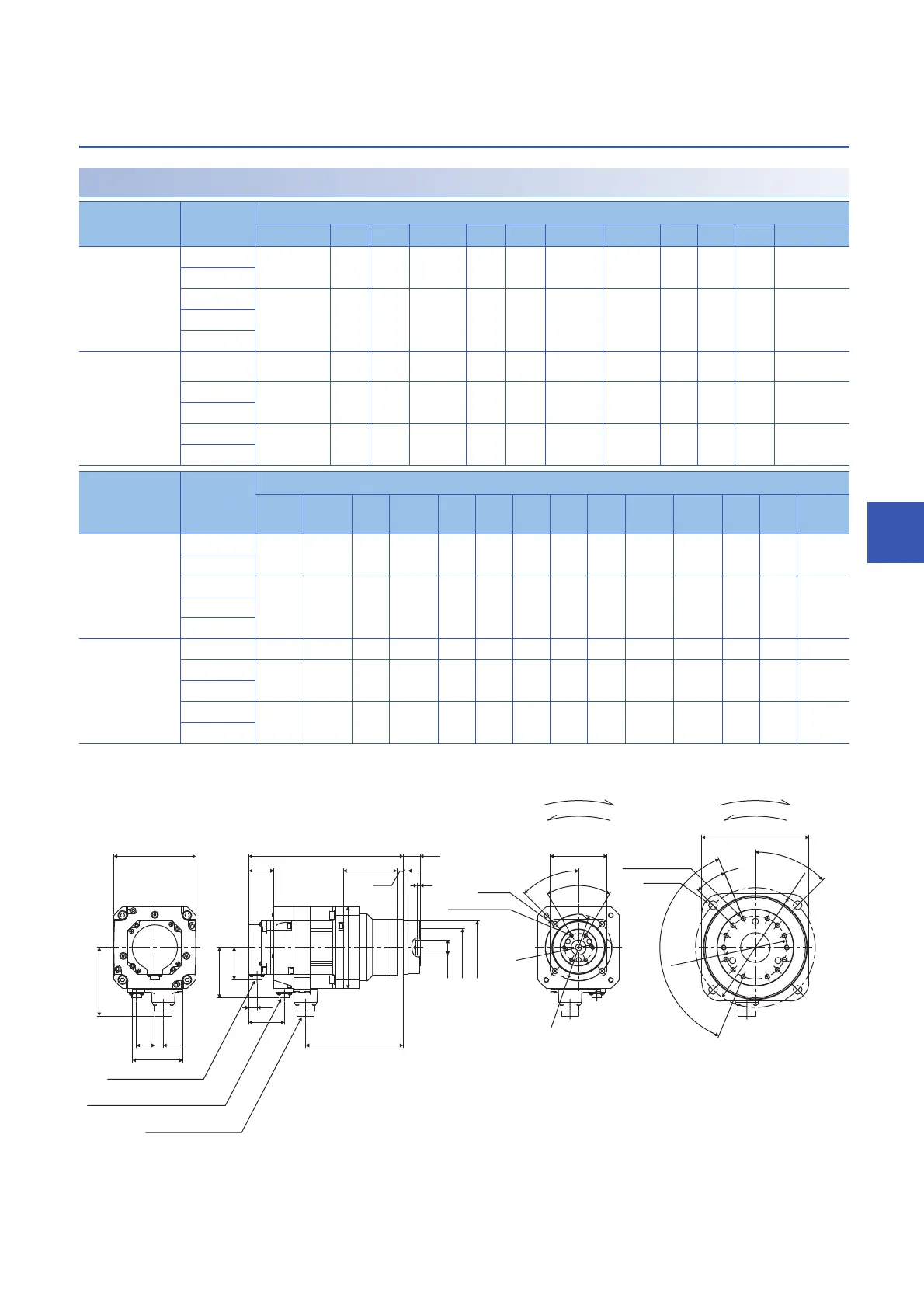
With flange-output type gear reducer for high precision
applications, flange mounting
HK-ST52(B)G5/HK-ST102(B)G5
*1 The values in ( ) of the dimensions are for the servo motors with an electromagnetic brake.
[Unit: mm]
*1 For the front view B, the screw positions are not placed equally in pitch around the circumference.
Model Reduction
ratio
Variable dimensions
*1
L LA LB LC LD LE LF LG LH LK LM LT
HK-ST52(B)G5 1/5 210.5 (245) 105 45 90 59 8 10 85 35.5 (39.5)
1/11
1/21 222.5 (257) 135 60 120 84 13 13 94 35.5 (39.5)
1/33
1/45
HK-ST102(B)G5 1/5 221.5 (256) 105 45 90 59 8 10 85 35.5 (39.5)
1/11 233.5 (268) 135 60 120 84 13 13 94 35.5 (39.5)
1/21
1/33 249.5 (284) 190 100 170 122 13 16 107 35.5 (39.5)
1/45
Model Reduction
ratio
Variable dimensions
*1
KL LP LW LS T N P R M KB KD KC KE Front
view
HK-ST52(B)G5 1/5 154.8 (56.5) 13.5 (35.5) 5 6 M6 10 9 108.8 (79.9) 130 80 A
1/11
1/21 166.8 (56.5) 13.5 (35.5) 5 6 M8 12 11 108.8 (79.9) 130 80 A
1/33
1/45
HK-ST102(B)G5 1/5 165.8 (56.5) 13.5 (35.5) 5 6 M6 10 9 108.8 (79.9) 130 80 A
1/11 177.8 (56.5) 13.5 (35.5) 5 6 M8 12 11 108.8 (79.9) 130 80 A
1/21
1/33 193.8 (56.5) 13.5 (35.5) 7 14 M8 12 14 108.8 (79.9) 130 80 B
1/45
27
+0.4
- 0.5
35
+0.4
- 0.5
27
+0.4
- 0.5
35
+0.4
- 0.5
53
+0.5
- 0.8
4-M
JL10-2E18-10PCE
(MS3102A18-10P)
CMV1-R2P
CMV1-R10P
60°
45°
LD
LF
6 × 22.5° (= 135°)
LE
LC
LG
LH
LK T
L
LT
50.9
KD
13
LP
KL
KB
LS
KE
KC
LW
LM
LA
LA
LB
4-M
45°
22.5°
LD
LB
Rotation
direction
Under reverse rotation command
Under forward rotation command
N-P screw hole
depth R
Power connector
Electromagnetic brake connector
Encoder connector
Rotation
direction
N-P screw hole
depth R
Under reverse rotation command
Under forward rotation command
Front view A
Front view B
*1
 Loading...


