FX Series Programmable Controlers Applied Instructions 5
5-195
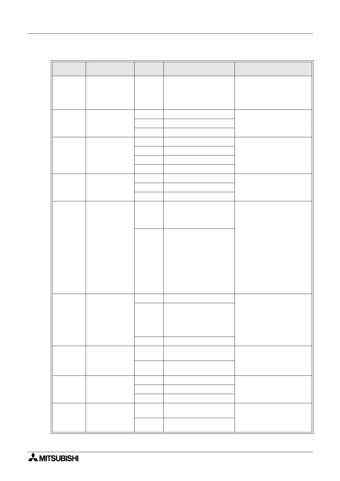
A500 series settings
Parameter
number
Description Set value Contents SettingforcommstoPLC
117 Station No. 0~31
Corresponds to the station No.
specified from the PU
connector.
If two or more inverters, set the
station No. at each inverter
Align setting with station number
in the sequence program
118
Communication
speed
48
4800bps
Normally select 192.
If high speed processing in PLC
use96or48
96
9600bps
192
19200bps
119
Stop bit length /
Data bit length
0
8databits/1stopbit
Select 10
1
8databits/2stopbits
10
7databits/1stopbit
11
7databits/2stopbits
120 Parity check
0
Absent
Select 2
1
Present (Odd)
2
Present (Even)
121
Number of
communication
retries
0,1~10
Set number of retries after data
receive error.
If this value is exceeded,
inverter comes to alarm stop
During trial run select 9999 and
perform adjustment.
During actual operation select
value in accordance with system
specifications
9999
(65535)
If a comms error occours,
inverter will not come to alarm
stop.
At this time inverter can be
coastedtostopbyMRSorRES
input.
During comms. error, the LF
signal is output to the open
collector output. Allocate one
terminal from Pr.190-195
122*
Communication
check time
interval
0
Comms not executed
While default value 0 is selected,
communications are disabled.
Select 9999, perform adjustment,
then select optimal value
0.1~999.8
Set comms check time interval.
If a no-communication state
persists for longer than the set
time, inverter comes to alarm
stop. See Note on page 195.
9999
Comms check suspended
123
Waiting time
setting
0~150
Set waiting time between data
transmission and response
Select 9999
9999
Waiting time set by
communication data
124 CR,LF selection
0
CR & LF instructions absent
Select 1
1
CR instruction present
2
CR & LF instructions present
342
E
2
PROM write
selection
0
Parameter write from computer
to EEPROM
Select either value according to
system specifications
1
Parameter write from computer
to RAM

 Loading...


