FX Series Programmable Controlers Applied Instructions 5
5-199
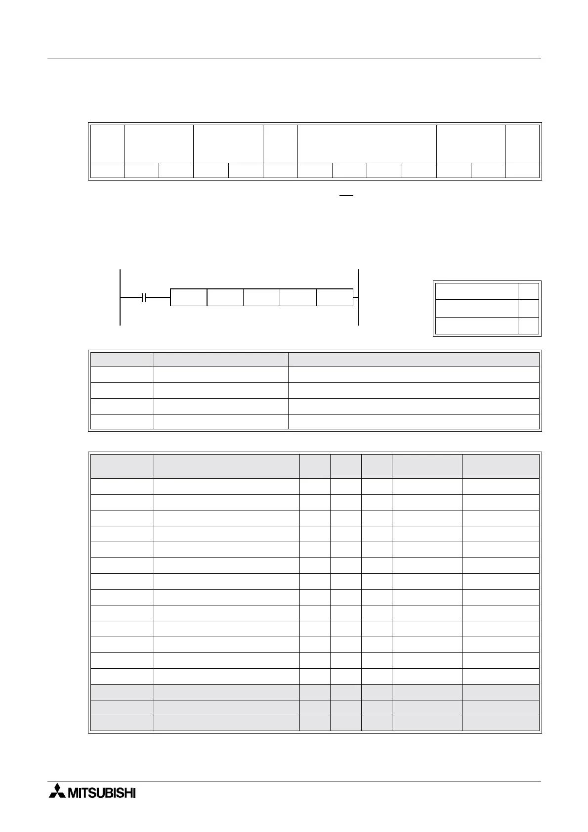
Example of transmission format when data is written from PLC to inverter
H30+H36+H38+H30+H30+H31+H32+H33+H34=H1C8
C=H43 8=H38
5.16.1.1.4 EXTR K10 - Monitoring operations (Inverter to PLC)
Details of S3
Note:
The shaded area is supported but is executed by EXTR K12.
ENQ
Inverter
station 6
Command
H80
Wait
time
=0
Data = 1234 SUM CR
H05 H30 H36 H38 H30 H30 H31 H32 H33 H34 H43 H38 H0D
16 Bit Operation
ü
32 Bit Operation
û
Pulse - P
û
Parameter Device type Parameter range
S1 K/H K10: function No. to monitor inverter operations
S2 KH, D Inverter station number (0 to 31)
S3 KH, D Inverter instructuion code (varies with model)
S4 D, KnY, KnM, KnS Read value storage destination
Instruction
Code
Monitor contents A500 E500 S500 Data digits Comms format
H7B Operation mode
üüü 4BðE|F
H6F Output frequency
üüü 4BðE|F
H70 Output current
üüü 4BðE|F
H71 Output voltage
üü 4BðE|F
H72 Special monitor
ü 4BðE|F
H73 Special monitor selection No.
ü 2BðE’ |F
H74 Alarm definition
üüü 4BðE|F
H75 Alarm definition
üüü 4BðE|F
H76 Alarm definition
üü 4BðE|F
H77 Alarm definition
üü 4BðE|F
H7A Inverter status monitor
üüü 2BðE’ |F
H6E Set frequency read (EEPROM)
ü 4BðE|F
H6D Set frequency read (RAM)
ü 4BðE|F
H00~H7B Parameter read ü ü ü 4 BðE|F
H7F Link parameter ü ü ü 2 BðE’ |F
H6C Second parameter change ü ü ü 2 BðE’ |F
EXTR K10 K6 H6F D100
S1 S2 S3 S4

 Loading...


