FX Series Programmable Controllers Assigning System Devices 9
9-5
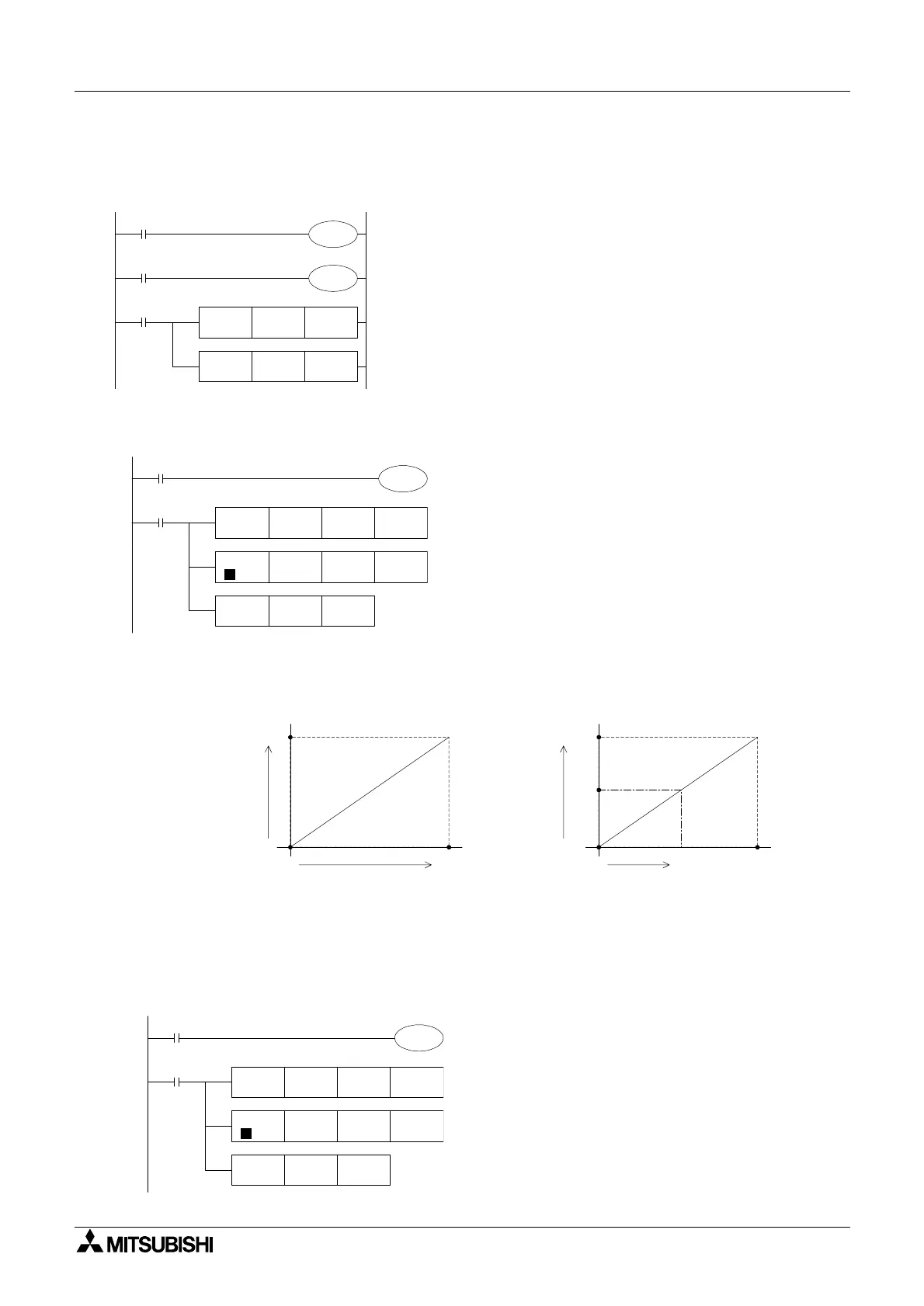
Example Application Program #1
Output an analog value in the range of 0 to 10 Volts when the digital value in the user program
is 0 ~ 10000.
D0 ranges from 0 ~10000. To convert D0 to the 0 ~ 4000 value needed for D8114:
D8114 = [D0 x 4000] / 10000 or [D x 2] /5
Example Application Program #2
An output of 0 ~ A [ 0 < A < 10] is desired in the program that is using a digital range of 0~4000
that is stored in register D10.
Because A is smaller than 10 Volts, the digital value of 0~4000 must be converted to a value of
0~A’ as shown in the graphs above. 4000/10V = A’/A or A’ = [4000/10] x A = 400 x A
D8114 = [A’] x (D10 / 4000) = [400 x A] x [D10 / 4000) = (A x D10) / 10.
If A = 8
M8001
M8000
M8000
FNC 12
MOV
D8112 D0
FNC 12
MOV
D8113 D2
M8112
M8113
Ch1 is set for the voltage input (0 to 10V).
Ch2 is set for the current input (4 to 20mA).
The digital value gained through AD conversion of Ch1 is stored at D0.
The digital value gained through AD conversion of Ch2 is stored at D2.
M8001
M8000
FNC 22
MUL
K2 D0
D2 K5
M8114
D2
D4
D4 D8114
FNC 23
DIV
D
FNC 12
MOV
0
0
A'
4000
Digital value
(D8114) for practical
analog output
Analog
output value
Digital value (D10) for output
0
0
10V
4000
Digital value (D8114) for output
A
A'
M8001
M8000
FNC 22
MUL
K8 D10
D12 K10
M8114
D12
D14
D14 D8114
FNC 23
DIV
D
FNC 12
MOV

 Loading...


