FX Series Programmable Controllers Assigning System Devices 9
9-6
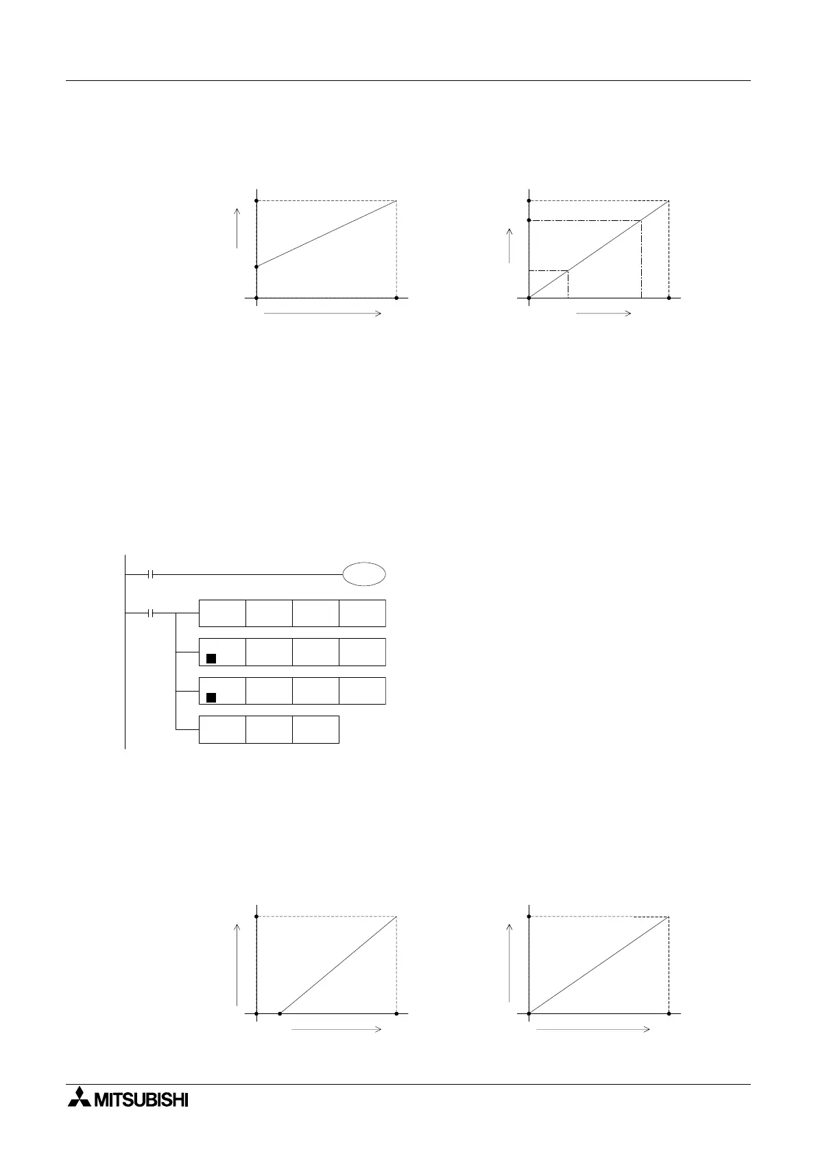
Example Application Program #3
The desired analog output is from values A to B where 0 < A < B < 10 and the digital values
range from 0 ~ 4000 in D20.
This example is equivalent to setting an offset and gain for the analog output.
The digital values must be converted to A’ and B’ per the graphs above.
[B-A]/[10-0]=[B’ -A’] / [4000 - 0], therefore [B’ -A’] = [B - A] x 400.
D8114 = [B’ -A’] x (D20 / 4000) + A’
B’ = 400 x B and A’ = 400 x A (see previous example programs for calculation)
D8114 = [400 x (B - A)/4000] x D20 + (400 x A)
D8114 = [(B-A)/10] x D20 + (400 x A)
If A = 2 and B = 5, see the programming example below
Example Application Program #4
In Voltage Output Mode, a digital range of values A ~ B is used in the program for an analog
output of 0 ~ 10 Volts. The digital range of A ~ B stored in D30 must be converted to 0 ~ 4000
before the correct analog value can be output.
0
0
B'
4000
Digital value
(D8114) for practical
analog output
Analog
output value
Digital value (D20) for output
0
0
10V
4000
Digital value (D8114) for output
A
A'
A'
B
B'
M8001
M8000
FNC 22
MUL
K3 D20
D24 K800
M8114
D22
D26
D26 D8114
FNC 20
ADD
D
FNC 12
MOV
D22 K10 D24
FNC 23
DIN
D
0
0
4000
B
Digital value
(D8114) for practical
analog output
Analog
output
value
Digital value (D30) for output
0
0
10V
4000
Digital value (D8114) for output
A

 Loading...


