FX Series Programmable Controllers Assigning System Devices 9
9-12
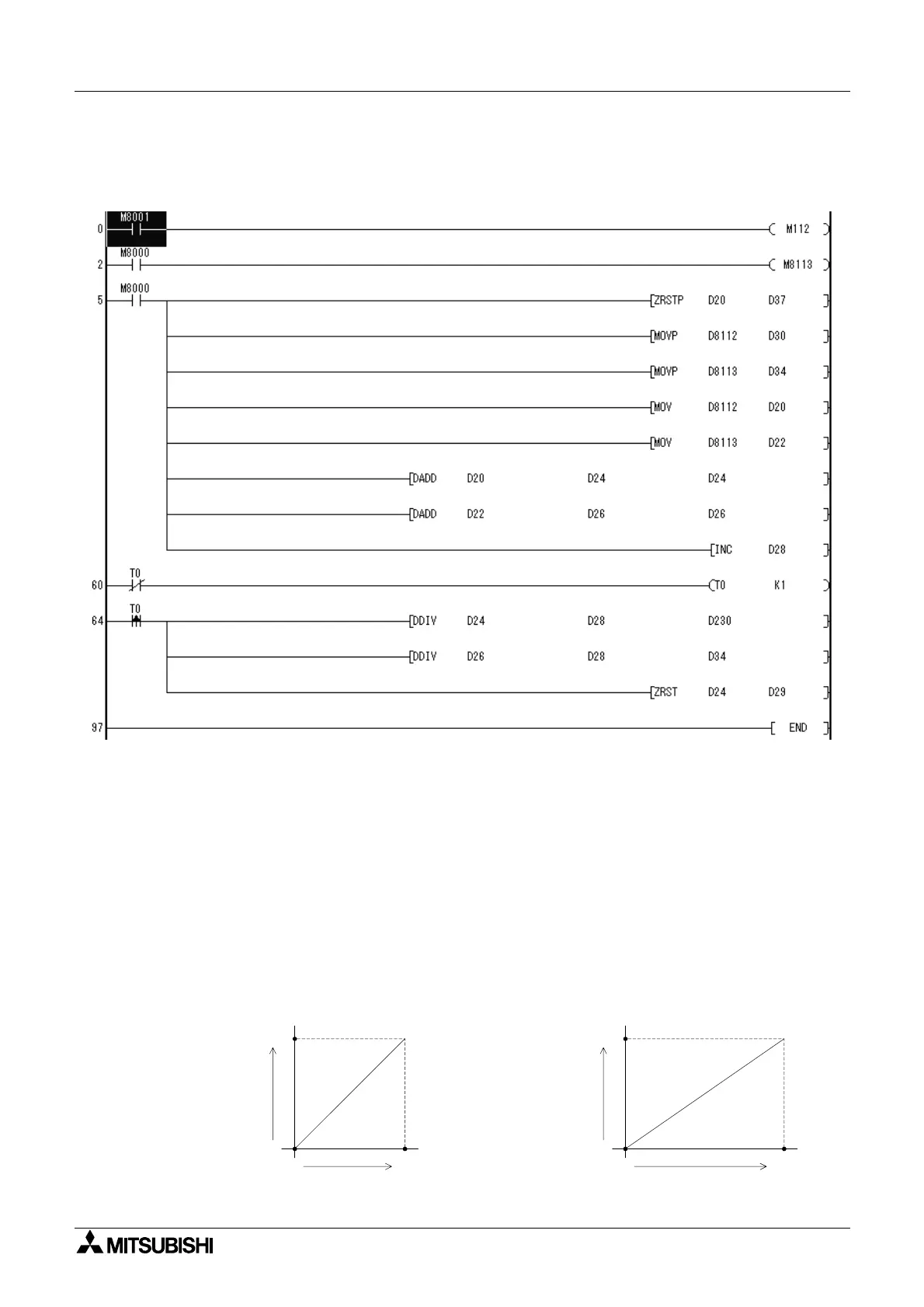
Basic Program 3
Ch1 is set to Current input, Ch2 is set to Voltage input, and the average converted digital value
over a set time period is stored in D30 and D34, respectively.
Example Application Programs
Because the 2AD does not have Offset and Gain capabilities, if values are required outside the
standard specification range, additional program commands are required to either multiply or
divide the conversion values.
When adjusting the conversion values, some of the resolution will be lost. The original range
of the analog input does not change.
Example Application Program #1
In Voltage input mode, the 2AD converts analog values from 0 ~ 10 Volts to a digital output of 0
~ 4000. If using a digital range of 0 ~ 10000 in the program, the 0 ~ 4000 output value must be
converted as shown in the programming example below. Digital values that are converted
from analog values are stored in D8112 or D8113.
0
0
10000
4000
Digital value (D10)
used in the program
0
0
4000
10V
Analog input
Digital output
(D8112, D8113)
D8112 or D8113 original AD conversion value

 Loading...


