FX Series Programmable Controllers Assigning System Devices 9
9-13
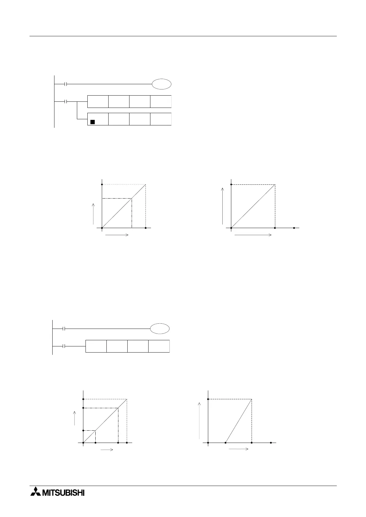
D10 = 10 x D8112 / 4, (D8113 would be used for Ch2)
The programming code for the Equation above is given below.
Example Application Program #2
In Voltage input mode, the 2AD converts analog values from 0 ~ 10 Volts to a digital output of 0
~ 4000. If using an analog range of 0 ~ A (where 0 < A < 10) by a digital output range of 0 ~
4000, the range must be converted from 0 ~A’ to 0 ~ 4000 as shown in the programming code
below.
If a digital value of 0 ~ 4000 is used in D20,
D20 = (4000) x (D8112 or D8113) / A’
4000 / (10 volts) = A’ / (A volts), therefore A’ = 400 x A
D20 = 4000 x (D8112 or D8113) / 400 x A
D20=10x(D8112orD8113)/AandifA=5
D20 = 2 x (D8112 or D8113)
Example Application Program #3
If using an analog range from A ~ B by a digital range of 0 ~ 4000, the range must be
converted from A’ ~B’ 0 ~ 4000 in the program as shown in the example below.
M8001
M8000
FNC 22
MUL
K10 D8112
FNC 23
DIV
D14 K4
M8112
D14
D10
D
0
0
4000
10V
Analog input
Digital AD
conversion
value
(D8112,D8113)
A
A'
0
0
4000
4000
A'
Digital value (D20)
used on the program
D8112 and D8113 original AD conversion value
M8001
M8000
FNC 22
MUL
K2 D8112
M8112
D20
0
0
4000
4000
D8112 or D8113 original AD conversion value
B'A'
Digital value (D30)
used in the program
0
0
4000
10V
Analog input
A'
B'
AB

 Loading...


