FX Series Programmable Controllers Points Of Technique 10
10-12
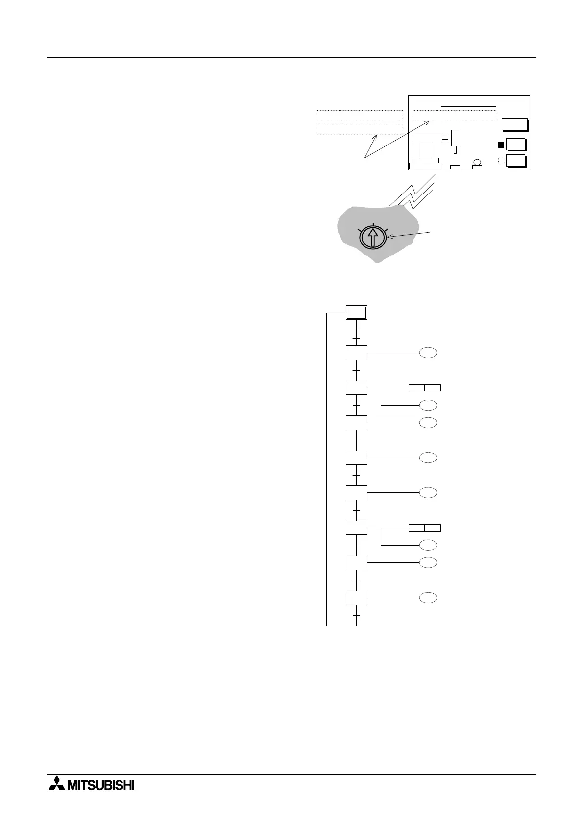
In this example these three modes are
selected by an external rotary switch. The
rotary switch is not connected to the PLC but
to the I/O bus on the rear of the DU unit.
The use of the rotary switch means that the
selected modes are mutually exclusive in
their operation. For an operator friendly
environment the currently selected mode is
displayed on the DU screen (again this could
be by use of the DUs ASCII function).
The start/ stop controls are touch keys on the
DU screen. When a mode is selected the
input received at the DU unit momentarily
activates one of the following auxiliary relays:
Rotary switch:
position 1 'Step' - Step operation: DU input I0,
controls bit device M32 position 2 'Cycle' -
Single cycle operation:
DU input I1, controls bit device M33 position 3
'Auto' - Automatic operation: DU input I2,
controls bit device M34
Key assignment for DU screen above:
Start = M36
Stop = M37
The program run in all three mode choices is
shown opposite. As noted earlier, the 'Step'
mode will require an operator to press the
'Start' key to start each new STL block. This
could be viewed as an additional transfer
condition between each state. However, the
user is not required to program this as the IST
instruction controls this operation
automatically.
The 'Cycle' mode will process the program
from STL step S2, all the way through until
STLstepS2isencounteredagain.Once
more the IST instruction ensures that only
one cycle is completed for each initial
activation of the 'Start' input.
Finally as suggested by the name, 'Auto'
mode will continuously cycle through the
program until the 'Stop' button is pressed.
The actual halting of the program cycling will
occur when the currently active cycle is
completed.
Automatic Mode
AB
Menu
Start
Stop
Automatic Operation
Single Cycle Operation
Stepped Operation
AUTOSTEP
CYCLE
Current
Operation
messages
Rotary switch input to
DU through I/O bus
(used to select mode).
Y0
X1
T0
Y2
X2
S 2
SET Y1
M8041
M8044
T0
K10
Y3
S 20
S 21
S 22
S 23
T1
RST Y1
T1
K10
X3
Y0
S 24
X1
S 25
Y2
S 26
X2
Y4
X4
S 27
Move grip down
Clamp is active
Move grip up
Move grip right
Move grip down
Clamp is not
active
Move grip up
Move grip left

 Loading...


