FX Series Programmable Controllers Points Of Technique 10
10-11
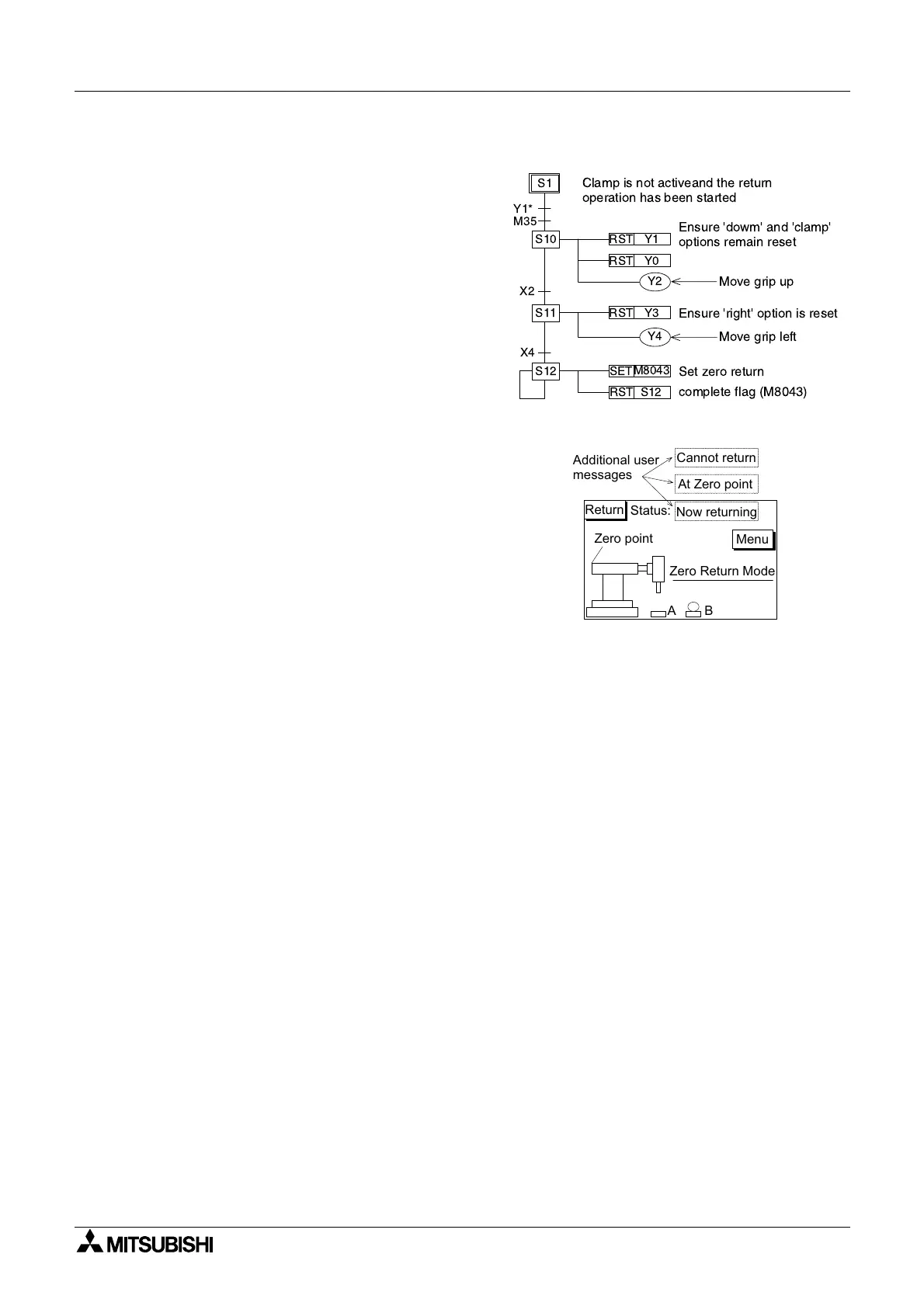
Zero Return Mode
This mode fulfills an initialization function by
returning the robot arm to a known position.
Once 'Z Return' has been selected from the
mode selection screen the bit device M35 is
ON. At this point the DU screen changes to the
'zero return' screen.
The actual zero return operation will then start
when the 'Return' push button is pressed
(activating M25) and the robots grip is not
active, i.e. Y1 is OFF (on the STL flow diagram
opposite Y1 OFF is shown as Y1*).
The DU unit could be used to report back the
status of the current returning operation. The
example screen shown opposite uses 3 variable
messages to indicate this status. The messages
could be text strings stored in the PLC which
are read and displayed by the DUs ASCII
option.
Once the zero point has been returned to, the operator would also return to the mode selection
screen. This is achieved by pressing the 'Menu' touch key. This then resets the zero return bit
device M31 which allows the DU screen change to take place.
Key assignment for DU screen above:
Return = M25
Menu = reset M31
Automatic Mode
Under this option there are three further mode selections. The available modes are:
Step Mode:
- The automatic program is stepped through - operation by operation, on command by the
user pressing the 'Start' button.
Cycle Mode:
- The automatic program is processed for one complete operational cycle. Each cycle is
initiated by pressing the 'Start' button. If the 'Stop' button is pressed, the program is
stopped immediately. To resume the cycle, the 'Start' button is pressed again.
Automatic Mode:
- A fully automatic, continuously cycling mode. The modes operation can be stopped by
pressing the 'stop' button. However, this will only take effect after completion of the
current cycle.
RST Y1
RST Y3
S10
S1
RST Y0
S11
S12
SET
M8043
RST S12
X4
X2
M35
Y1*
Y2
Y4
Clamp is not activeand the return
operation has been started
Ensure 'dowm' and 'clamp'
options remain reset
Move grip up
Ensure 'right' option is reset
Set zero return
Move grip left
complete flag (M8043)
Zero Return Mode
AB
Menu
Return
Status:
Now returning
At Zero point
Cannot return
Zero point
Additional user
messages

 Loading...


