142
FX3UC Series Programmable Controllers
User’s Manual - Hardware Edition
5 Input Specifications and External wiring
5.2 24V DC Input Type
5.2.4 Instructions for connecting input devices
The input current of this PLC is 5 to 7mA/24V DC.
Use input devices applicable to this minute current.
If no-voltage contacts (switches) for large current are used, contact failure may occur.
<Example> Products of OMRON
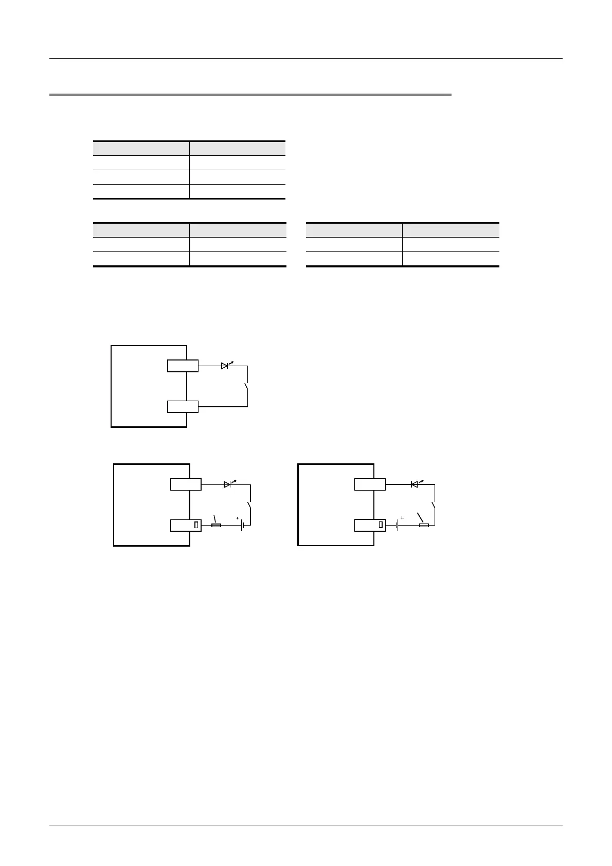
1. In the case of input device with built-in series diode
The voltage drop of the series diode should be approx. 4V or less.
When lead switches with a series LED are used, up to two switches can be connected in series.
Also make sure that the input current is over the input-sensing level while the switches are ON.
• Examples of wiring (Dedicated to sink input types only)
• Examples of wiring (Common to both sink and source input types)
Input number Input current
X000 to X005 6mA/24V DC
X006, X007 7mA/24V DC
X010 or more 5mA/24V DC
Type Model name Type Model name
Microswitch Models Z, V and D2RV Operation switch Model A3P
Proximity switch Model TL Photoelectric switch Model E3S
PLC
X
LED
COM
PLC
X
LED
24V DC
Fuse
COM
Sink input wiring
PLC
X
LED
24V DC
Fuse
COM
Source input wiring
 Loading...


