143
FX3UC Series Programmable Controllers
User’s Manual - Hardware Edition
5 Input Specifications and External wiring
5.2 24V DC Input Type
1
Outline
2
External
Dimensions
3
Generic
Specifications
4
Power Supply
Specifications
5
Input
Specifications
6
Output
Specifications
7
Examples of
Wiring for
Various Uses
8
Terminal Block
9
CC-Link/LT
Master FX
3UC
(LT only)
10
Display module
FX
3UC
(LT only)
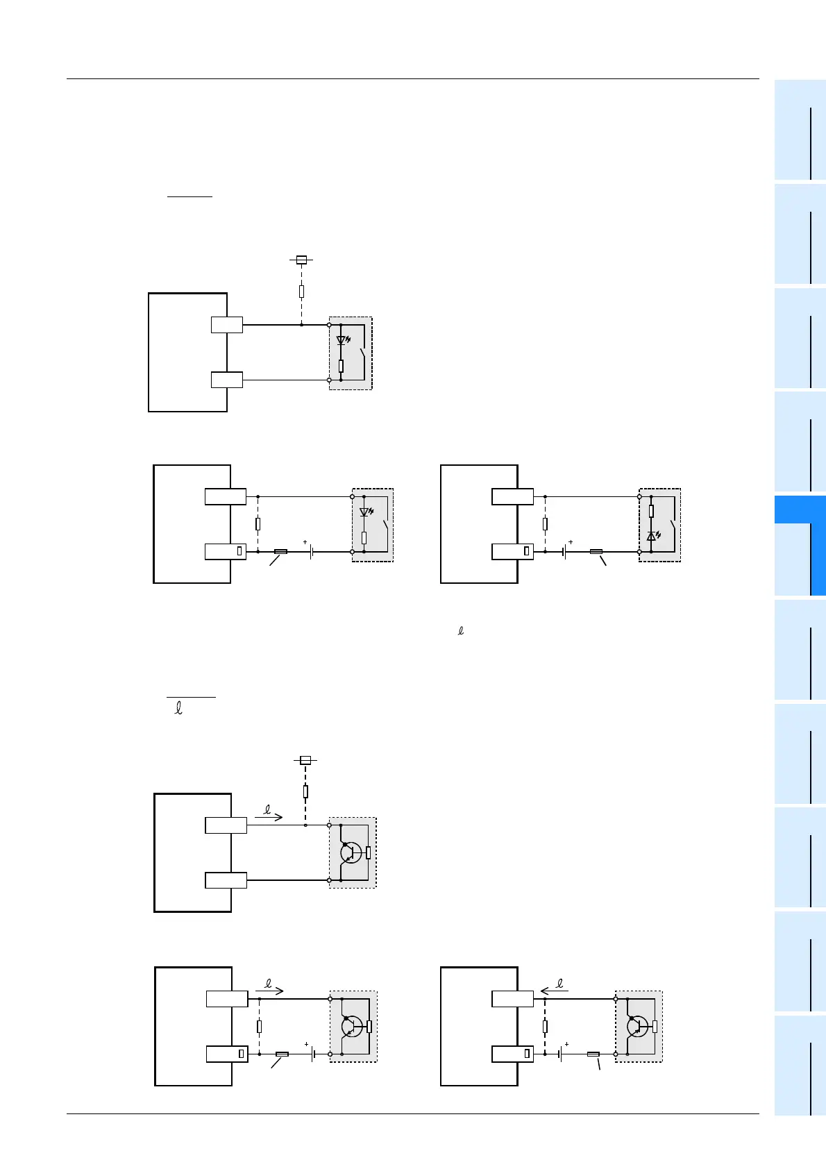
2. In the case of input device with built-in parallel resistance
Use a device having a parallel resistance, Rp, of 15kΩ or more.
If the resistance is less than 15kΩ, connect a bleeder resistance, Rb, obtained by the following formula as
shown in the following figure.
• Examples of wiring (Dedicated to sink input types only)
• Examples of wiring (Common to both sink and source input types)
3. In the case of 2-wire proximity switch
Use a two-wire proximity switch whose leakage current, I , is 1.5mA or less when the switch is off.
When the current is 1.5mA or more, connect a bleeder resistance, Rb, determined by the following formula as
shown in the following figure.
• Examples of wiring (Dedicated to sink input types only)
• Examples of wiring (Common to both sink and source input types)
Rb
4Rp
15-Rp
(k
Ω
)
≤
PLC
X
Rp
+24V
Rb
COM
Bleeder
resistance
15k
Ω
or
more
PLC
X
Rp
Rb
COM
24V DC
Fuse
Sink input wiring
Bleeder
resistance
15k
Ω
or
more
PLC
X
Rp
Rb
COM
24V DC
Fuse
Source input wiring
Bleeder
resistance
15k
Ω
or
more
Rb
6
I -1.5
(k
Ω
)
≤
PLC
X
COM
+24V
Rb
I
Bleeder
resistance
2-wire
proximity
sensor
PLC
X
I
Rb
24V DC
Fuse
Source input wiring
COM
Bleeder
resistance
2-wire
proximity
sensor
PLC
X
I
Rb
24V DC
Fuse
Sink input wiring
COM
Bleeder
resistance
2-wire
proximity
sensor
 Loading...


