181
FX3UC Series Programmable Controllers
User’s Manual - Hardware Edition
6 Output Specification and External Wiring
6.3 Relay Output [FX2NC/FX0N/FX2N Extension Blocks]
1
Outline
2
External
Dimensions
3
Generic
Specifications
4
Power Supply
Specifications
5
Input
Specifications
6
Output
Specifications
7
Examples of
Wiring for
Various Uses
8
Terminal Block
9
CC-Link/LT
Master FX
3UC
(LT only)
10
Display module
FX
3UC
(LT only)
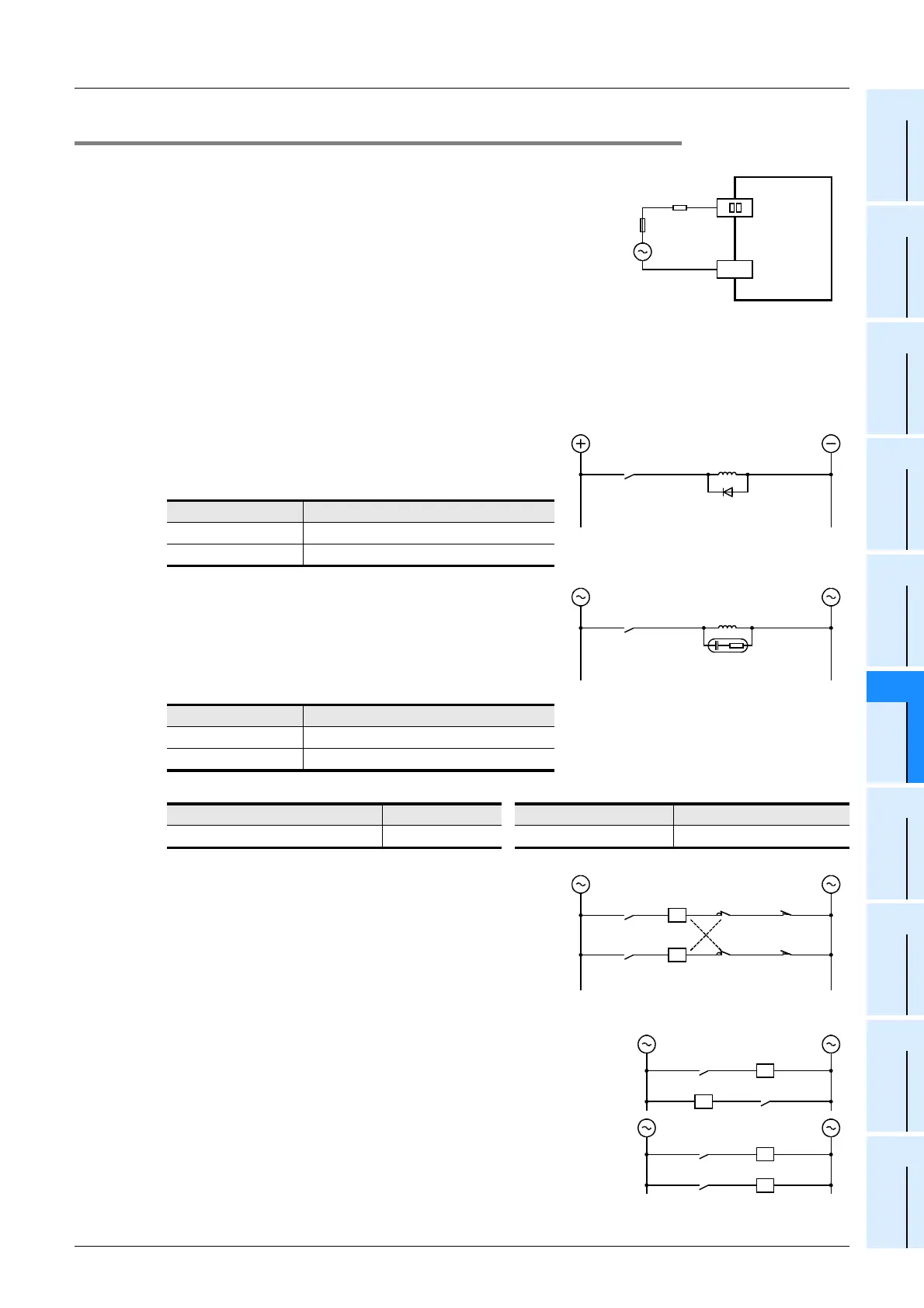
6.3.4 External wiring precautions
1. Protection circuit for load short-circuiting
A short-circuit at a load connected to an output terminal could
cause burnout at the output element or the PCB. To prevent
this, a protection fuse should be inserted at the output.
2. Contact protection circuit for inductive loads
An internal protection circuit for the relays is not provided for the relay output circuit in the extension blocks. It
is recommended to use inductive loads with built-in protection circuits. When using loads without built-in
protection circuits, insert an external contact protection circuit, etc. to reduce noise and extend the product
life.
1) DC circuit
Connect a diode in parallel with the load.
The diode (for commutation) must comply with the following
specifications.
2) AC circuit
Connect the surge absorber (combined CR components
such as a surge killer and spark killer, etc.) parallel to the
load.
Select the rated voltage of a surge absorber that is suitable
for the load being used. Refer to the table below for other
specifications.
Reference
3. Interlock
For loads such as forward/reverse contactors, etc., where a
hazardous condition could result if switched ON simultaneously,
an external interlock should be provided for interlocking the
PLC’s internal programs as shown to the right.
4. In-phase
PLC output contacts (*) should be used in an "in-phase"
manner.
Item Guide
Reverse voltage 5 to 10 times the load voltage
Forward current Load current or more
Item Guide
Electrostatic capacity Approx. 0.1µF
Resistance value Approx. 100 to 200Ω
Manufacturer Model name Manufacturer Model name
Okaya Electric Industries Co., Ltd. CR-10201 Rubycon Corporation 250MCRA104100M B0325
PLC
COM1
Load
Fuse
Y 0
Inductive load
PLC output
contact
Diode
(for commutation)
Inductive load
Surge
absorber
PLC output
contact
Inter-
lock
PLC output
contact
PLC output
contact
Limit of normal
rotation
Limit of reverse
rotation
*
Bad
Good
*
*
*
 Loading...


