193
FX3UC Series Programmable Controllers
User’s Manual - Hardware Edition
7 Examples of Wiring for Various Uses
7.4 Digital Switch [DSW (FNC 72)/BIN (FNC 19)]
1
Outline
2
External
Dimensions
3
Generic
Specifications
4
Power Supply
Specifications
5
Input
Specifications
6
Output
Specifications
7
Examples of
Wiring for
Various Uses
8
Terminal Block
9
CC-Link/LT
Master FX
3UC
(LT only)
10
Display module
FX
3UC
(LT only)
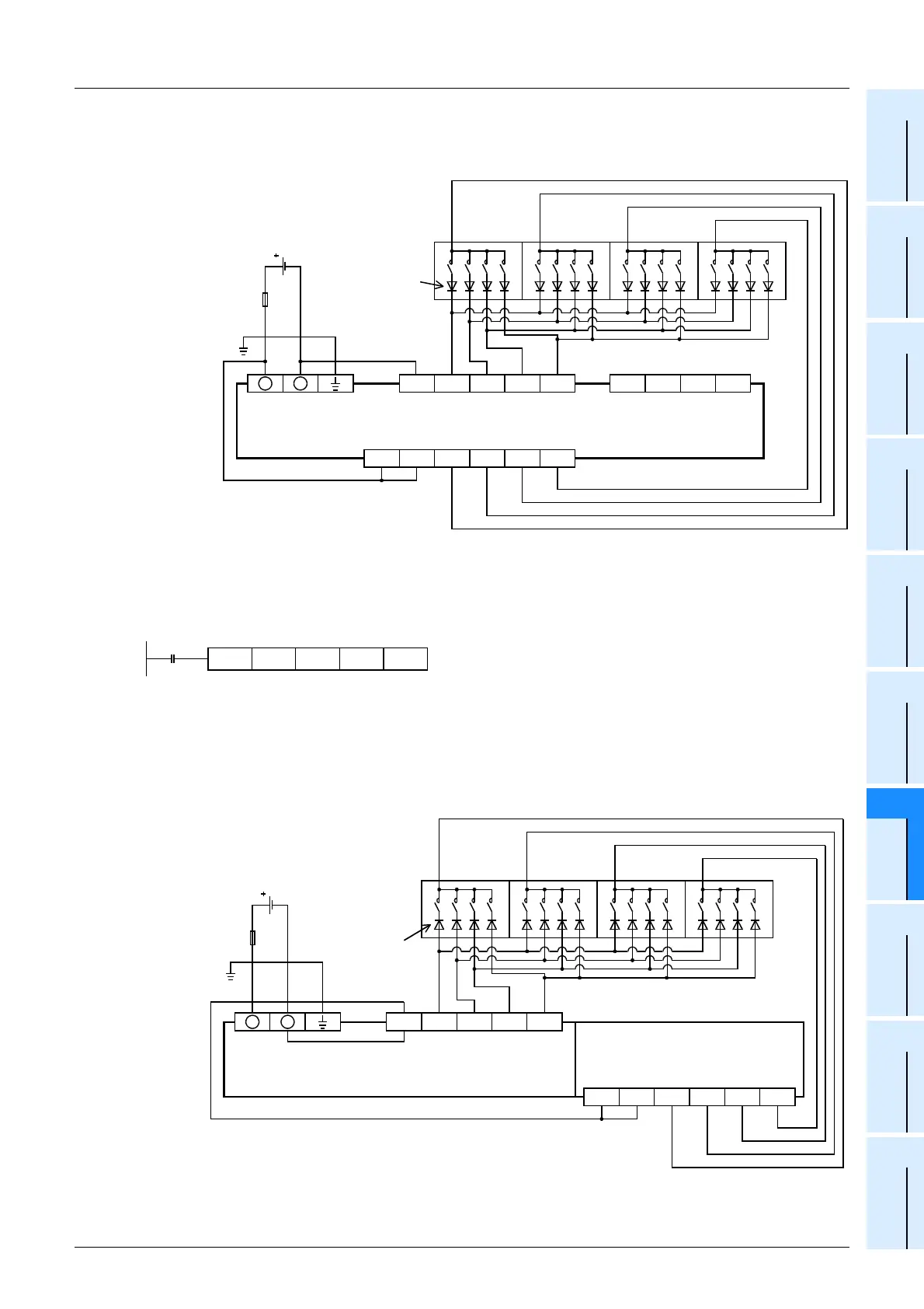
2) In the case of source wiring
Use the sink/source common input, source only output (transistor output) type main unit.
The wiring example is the FX
3UC-32MT/DSS.
2. Main unit + Output extension block
Example of program
Example of wiring
1) In the case of sink wiring
Use the sink only input, sink only output type main unit and a transistor output (sink only output) type
output extension block.
The wiring example is the [FX
3UC-32MT/D or FX3UC-32MT-LT] + output extension block [FX2NC-
16EYT].
COM0
X010 X011 X012 X013 X015X014 X016 X017
+V0 Y010 Y011 Y012 Y013
Source input
FX
3UC
-32MT/DSS
1248
10
3
10
2
10
1
10
0
10
3
10
2
10
1
10
0
0.1A 50V
diode is
necessary.
Digital
switch of
BCD
Transistor output (source)
+V0
+
-
Fuse
24V DC
Class D
grounding*
* The grounding resistance should be 100
Ω
or less.
DSW
M8000
X010 Y020 D100 K1
COM0
X010 X011 X012 X013
COM1
Y020 Y021 Y022 Y023
Sink input
1248
10
3
10
2
10
1
10
0
10
3
10
2
10
1
10
0
0.1A 50V
diode is
necessary.
Digital
switch of
BCD
Transistor output (sink)
COM1
+
-
Fuse
24V DC
Class D
grounding*
FX
2NC
-16EYT
FX
3UC
-32MT/D
* The grounding resistance should be 100
Ω
or less.
 Loading...


