192
FX3UC Series Programmable Controllers
User’s Manual - Hardware Edition
7 Examples of Wiring for Various Uses
7.4 Digital Switch [DSW (FNC 72)/BIN (FNC 19)]
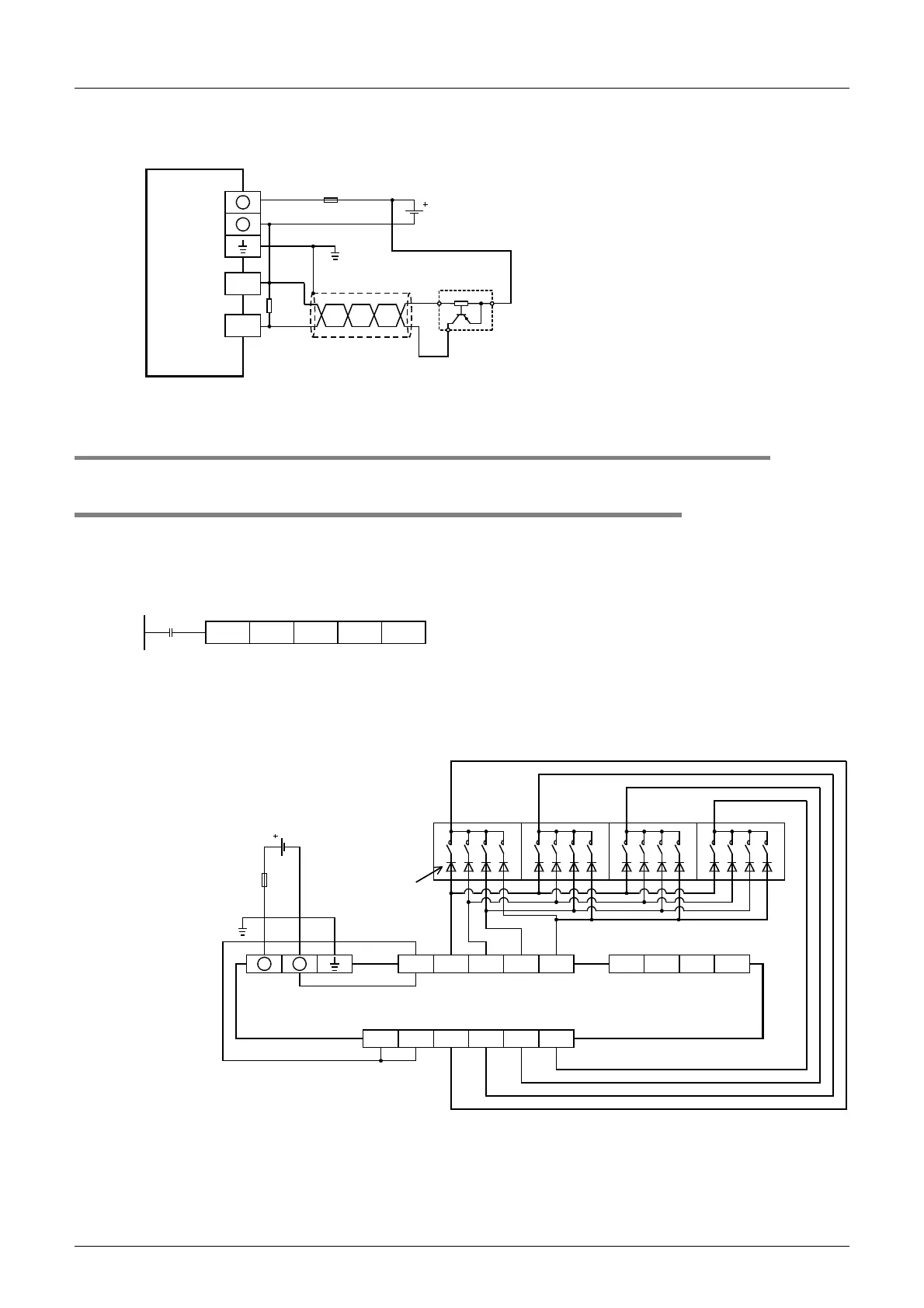
2. PNP open collector transistor output three-wire sensor
In case of the FX3UC-MT/DSS [Source input wiring]
7.4 Digital Switch [DSW (FNC 72)/BIN (FNC 19)]
7.4.1 When DSW instructions are used
Examples of wiring for capturing values from a 4-digit digital switch to the data register D100 are given below.
1. Main unit
Example of program
Example of wiring
1) In the case of sink wiring
Use the sink only input, sink only output type main unit.
The wiring example is the FX
3UC-32MT/D or FX3UC-32MT-LT.
PLC
Fuse
Class D
grounding*
24V DC
+
-
X000
COM0
Three-wire
sensor
* The grounding resistance should be 100
Ω
or less.
1.5
k
Ω
DSW
M8000
X010 Y010 D100 K1
COM X010 X011 X012 X013 X015X014 X016 X017
COM1
Y010 Y011 Y012 Y013
Sink input
FX
3UC
-32MT/D
FX
3UC
-32MT-LT
1248
10
3
10
2
10
1
10
0
10
3
10
2
10
1
10
0
0.1A 50V
diode is
necessary.
Digital
switch of
BCD
Transistor output (sink)
COM1
+
-
Fuse
24V DC
Class D
grounding*
* The grounding resistance should be 100
Ω
or less.
 Loading...


