191
FX3UC Series Programmable Controllers
User’s Manual - Hardware Edition
7 Examples of Wiring for Various Uses
7.3 Input Interruption - With Delay Function, Pulse Catch
1
Outline
2
External
Dimensions
3
Generic
Specifications
4
Power Supply
Specifications
5
Input
Specifications
6
Output
Specifications
7
Examples of
Wiring for
Various Uses
8
Terminal Block
9
CC-Link/LT
Master FX
3UC
(LT only)
10
Display module
FX
3UC
(LT only)
7.3 Input Interruption - With Delay Function, Pulse Catch
This section shows wiring examples for input interruption (I000 or I001) using X000.
When using another input interruption or pulse catch, perform wiring in reference to the figures below.
→ For input allocation in input interruption, refer to Section 5.6.
→ For input allocation in oulse catch, refer to Section 5.7.
Caution
Use shielded twisted-pair cables for connecting cables.
Ground the shield of each shielded cable only on the PLC side.
Observe the following items for input interruption or pulse catch using the inputs X000 to X005.
• The wiring length should be 5m (16.4") or less.
• Connect a bleeder resistance of 1.5kΩ (1W or more) to the input terminal, so that the sum of the load
current of the open collector transistor output on the mating device side and the input current of the main
unit is 20mA or more.
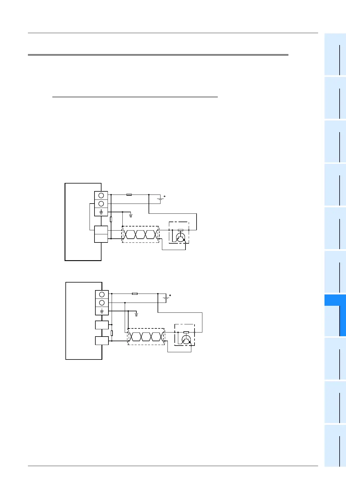
1. NPN open collector transistor output three-wire sensor
1) In case of the FX3UC-MT/D, FX3UC-32MT-LT
2) In case of the FX
3UC-MT/DSS [Sink input wiring]
PLC
Fuse
Class D
grounding*
24V DC
+
-
X000
COM
* The grounding resistance should be 100
Ω
or less.
1.5
k
Ω
Three-wire
sensor
PLC
Fuse
Class D
grounding*
24V DC
1.5
k
Ω
+
-
X000
COM0
Three-wire
sensor
* The grounding resistance should be 100
Ω
or less.
 Loading...


