222
FX3UC Series Programmable Controllers
User’s Manual - Hardware Edition
8 Terminal Block Specifications and External Wiring
8.5 FX-16E-TB/FX-32E-TB
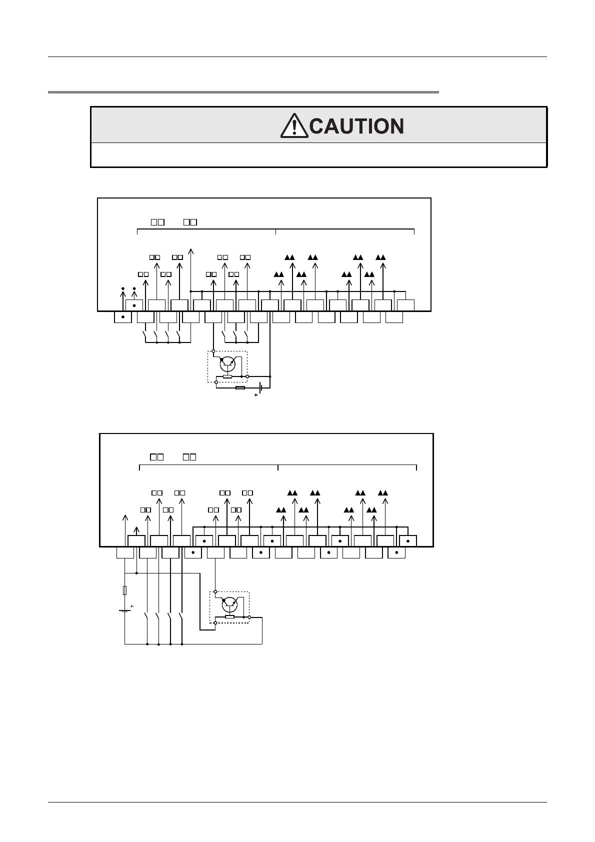
8.5.2 Example of input external wiring [sink wiring]
1. When connected to the FX3UC-MT/D, FX3UC-32MT-LT and FX2NC-EX input connector.
2. When connected to an FX
2N-16EX-C input connector
WIRING PRECAUTIONS
• Before cleaning or retightening terminals cut off all phases of the power supply externally.
Failure to do so may cause electric shock.
0 to
7 (Higher Nos.)0 to 7 (Lower Nos.)
1
COM
3
4
5
60 2
7 1 3
0 2 4
5
6
7
COM
COM
COM
COM
COM
COM
COM
Vacant
terminal
7
6
5
4
3
2
1
0 0
1
2
3
4
5
6
7
24V DC
PLC's
input No.
Fuse
COM
Three-
wire
sensor
NPN
1 3
4
5
60 2
7 1 3
0 2 4
5
6
7
24+
7
6
5
4
3
2
1
0 0
1
2
3
4
5
6
7
24V
DC
Input numbers in the
FX
2N
-16EX-C
24+
24+
24+
0 to
7 (Higher Nos.)0 to 7 (Lower Nos.)
Fuse
Three-
wire
sensor
NPN
 Loading...


