225
FX3UC Series Programmable Controllers
User’s Manual - Hardware Edition
8 Terminal Block Specifications and External Wiring
8.6 FX-16E-TB/UL, FX-32E-TB/UL
1
Outline
2
External
Dimensions
3
Generic
Specifications
4
Power Supply
Specifications
5
Input
Specifications
6
Output
Specifications
7
Examples of
Wiring for
Various Uses
8
Terminal Block
9
CC-Link/LT
Master FX
3UC
(LT only)
10
Display module
FX
3UC
(LT only)
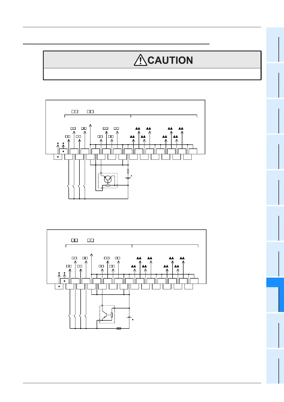
8.6.2 Example of input external wiring [Sink/Source wiring]
1. Connection to the input connector in the FX3UC-MT/DSS or FX2NC-EX-DS for sink
wiring
2. Connection to the input connector in the FX
3UC-MT/DSS or FX2NC-EX-DS for source
wiring
WIRING PRECAUTIONS
• Before cleaning or retightening terminals cut off all phases of the power supply externally.
Failure to do so may cause electric shock.
0 to
7 (Higher Nos.)0 to 7 (Lower Nos.)
1
COM
3
4
5
60 2
7 1 3
0 2 4
5
6
7
COM
COM
COM
COM
COM
COM
COM
7
6
5
4
3
2
1
0 0
1
2
3
4
5
6
7
24V DC
COM0
*1
*1."COM1" or "COM2" in accordance with connected connector
Fuse
Vacant
terminal
PLC's
input No.
Three-wire
sensor NPN
0 to
7 (Higher Nos.)0 to 7 (Lower Nos.)
1
COM
3
4
5
60 2
7 1 3
0 2 4
5
6
7
COM
COM
COM
COM
COM
COM
COM
7
6
5
4
3
2
1
0 0
1
2
3
4
5
6
7
24V DC
*1."COM1" or "COM2" in accordance with connected connector
Fuse
COM0
*1
Vacant
terminal
PLC's
input No.
Three-wire
sensor PNP
 Loading...


