227
FX3UC Series Programmable Controllers
User’s Manual - Hardware Edition
8 Terminal Block Specifications and External Wiring
8.7 FX-16EX-A1-TB
1
Outline
2
External
Dimensions
3
Generic
Specifications
4
Power Supply
Specifications
5
Input
Specifications
6
Output
Specifications
7
Examples of
Wiring for
Various Uses
8
Terminal Block
9
CC-Link/LT
Master FX
3UC
(LT only)
10
Display module
FX
3UC
(LT only)
8.7 FX-16EX-A1-TB
Connect the FX-16EX-A1-TB to the input connector in the main unit or extension block shown in the table
below.
The applications shown below are not supported.
8.7.1 Specifications
*1. This response time does not include the response delay at the PLC.
*2. 3.9W (160mA, 24V DC) is required when connected to the FX
2N-16EX-C.
Input connector
Connectable models FX
3UC-MT/D, FX3UC-32MT-LT, FX2NC-EX, FX2N-16EX-C
Unsupported Applications
Time division input
Input matrix (MTR) instruction, hexadecimal input (HKY) instruction, digital switch (DSW)
instruction, arrow switch (ARWS) instruction
High-speed
processing
High-speed counter, input interruption, pulse catch, speed detection (SPD) instruction
Other
Refresh and filter adjust (REFF) instruction, ten key input (TKY) instruction, absolute current
value read (ABS) instruction
Item FX-16EX-A1-TB
Connection form
Terminal block (M3.5 screw)
The connection with the PLC is the connector.
input type AC input
Input signal voltage 100 to 120V AC +10%, -15% 50/60 Hz
Input signal current
4.7mA/100V AC 50 Hz
6.2mA/110V AC 60 Hz
Input impedance
Approx. 21 kΩ/50 Hz
Approx. 18 kΩ/60 Hz
Input sensitivity
ON 3.8mA/80V AC or more
OFF 1.7mA/30V AC or more
Response time
*1
25 to 30ms
Input signal format Voltage contact
Circuit isolation Photocoupler isolation
Input operation display No input LEDs (equipped with 24V power supply LED indicator)
Power consumption
1.2W (48mA 24V DC)
*2
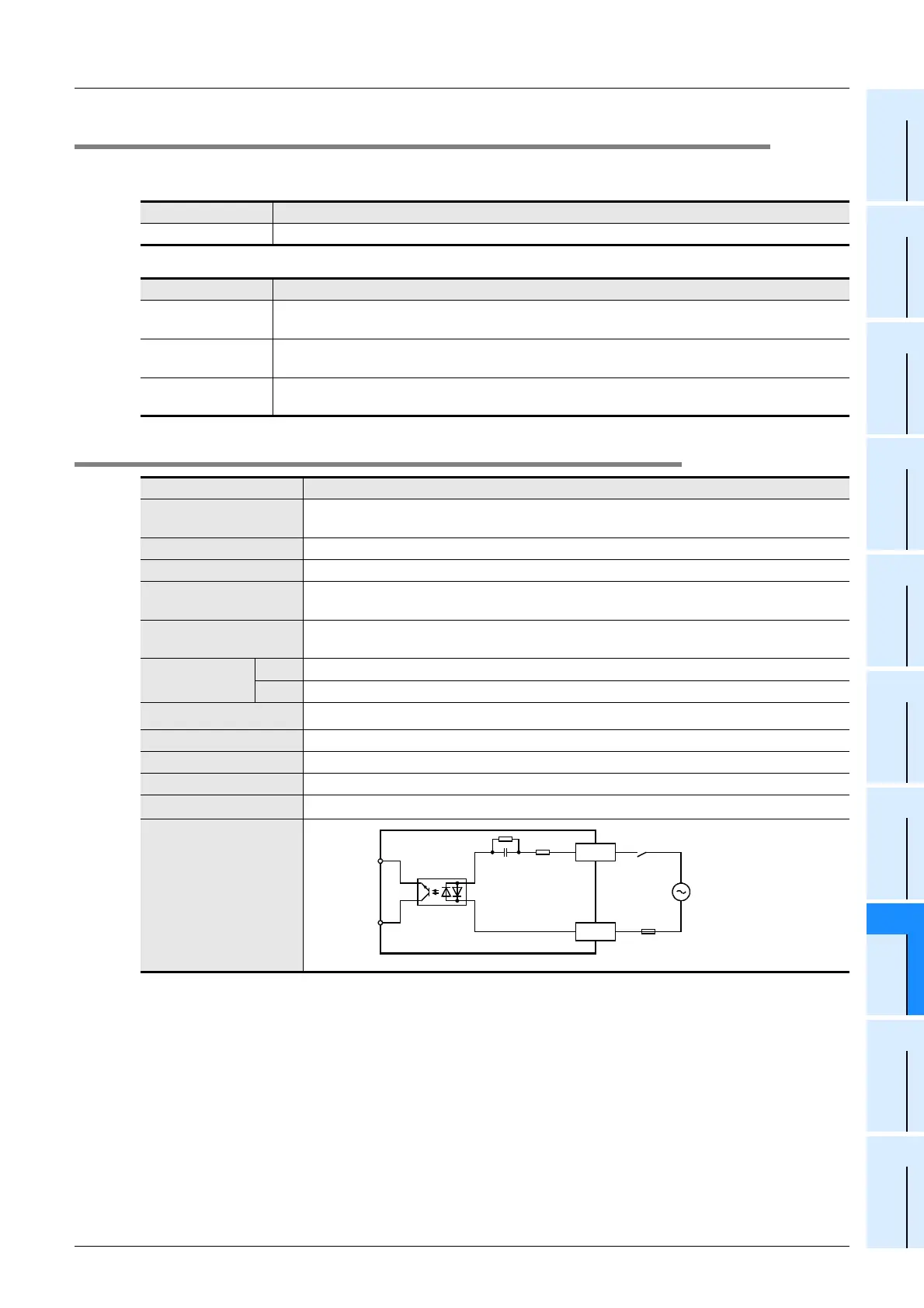
Input/output circuitry
0 to 7
COMn
Photo-
coupler
100V
AC
External wiring
CN1
Connector
side
Fuse
Terminal block
 Loading...


