6 - 4
6.3 Mounting Position
1
OVERVIEW
2
SYSTEM
CONFIGURATION
3
SPECIFICATIONS
4
PART NAME
5
EMC DIRECTIVE
6
INSTALLATION
7
WIRING
8
OPTION
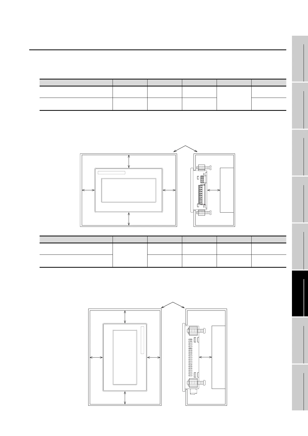
6.3 Mounting Position
When mounting the GOT, the following clearances must be maintained from other structures and devices.
Horizontal format
*1 50 mm (1.97”) or more if an RS-232/USB conversion adaptor is used.
*2 80 mm (3.14”) or more if a PC connection cable is used or if an RS-232 interface for PC is used to connect
multiple GOT units.
50 mm (1.97”) or more if an RS-232/USB conversion adaptor is used and is connected to the RS-232 interface
for PC.
Vertical format
*1 50 mm (1.97”) or more if an RS-232/USB conversion adaptor is used.
*2 80 mm (3.14”) or more if a PC connection cable is used or if an RS-232 interface for PC is used to connect
multiple GOT units.
50 mm (1.97”) or more if an RS-232/USB conversion adaptor is used and is connected to the RS-232 interface
for PC.
Installation Environment A B C D E
In the presence of radiated-noise or
heat-generating equipment nearby
50 mm (1.97”)
or more
50 mm (1.97”)
or more
50 mm (1.97”)
or more
50 mm (1.97”)
or more
80 mm (3.14”)
or more
In the absence of radiated-noise or
heat-generating equipment nearby
20 mm (0.79”)
or more
*1
20 mm (0.79”)
or more
20 mm (0.79”)
or more
20 mm (0.79”)
or more
*2
Installation Environment A B C D E
In the presence of radiated-noise or
heat-generating equipment nearby
50 mm (1.97”)
or more
50 mm (1.97”)
or more
50 mm (1.97”)
or more
50 mm (1.97”)
or more
80 mm (3.14”)
or more
In the absence of radiated-noise or
heat-generating equipment nearby
20 mm (0.79”)
or more
20 mm (0.79”)
or more
*1
20 mm (0.79”)
or more
20 mm (0.79”)
or more
*2
MITSUBISHI
GOT
1000
Other device or control panel
A
B
C
DE
Other device or control panel
MITSUBISHI
GOT
1000
A
B
C
DE
WWW.NNC.IR
 Loading...


